Forces and motion
Motion
Constant acceleration equations
The constant acceleration equations use the following variables
- Final velocity
- Initial velocity
- Acceleration
- Time for the change in velocity
- Displacement during the velocity change
The final equation is not required for this course.
Free fall and projectile motion
Free fall The acceleration a body feels when falling in the presence of a gravitational field
Objects of different masses fall at the same rate under the influence of gravity, this is because the acceleration of a body is directly proportional to the net force, but inversely proportional to its mass.
Trajectory The path of any moving object
Projectile An object that is given an initial force, and then allowed to move freely through space
Parabola The name given to the shape of a curve which a projectile follows when gravity is the only force acting upon it
In the real world air resistance also acts on projectiles, however this is ignored in order to allow the problems to be solved using the constant acceleration equations.
To solve a problem, the components of motion are split into two parts, horizontal and vertical.
Measurement of g
Light gate A device which measures the time between a beam of light being broken and being restored.
Motion sensor Record displacement at regular time intervals
Both of these devices can be used to determine an experimental value for .
Measurements can either be direct or indirect
- Direct measurement is measurement which does not require manipulation, such as time a falling object
- Indirect measurement requires manipulation, such as measuring the period of pendulum and rearranging to find
When explaining an investigation, state the following
- The measurements to be taken
- The equipment with which to take the measurements
- The variables required to determine
- The sources of uncertainty in the measurements
- The possible methods to minimise uncertainty
Investigation- Use of a trap door and an electromagnet to determine
Equipment
An electromagnet supports a steel ball.
The electromagnet is on the same circuit as a timer.
Procedure
When a switch is toggled the ball begins to fall a known distance, and the timer on the same circuit begins.
The ball falls onto a trap door, stopping the timer.
Calculation
The variables are the distance fallen, s, and the time taken, t.
Using the constant acceleration acceleration
For any values of s and t we can then find a value for acceleration due to gravity.
Alternatively we could use the inferior and inaccurate method of drawing a graph of against which would have a gradient of .
Methods to increase accuracy and reduce error
In order to increase the accuracy of the experiment we could take repeat readings to find a mean value for , and measure t across different heights.
Car stopping distances
Stopping distance The total distance that a vehicle travels before it stops
Thinking distance The distance a vehicle travels between the operator seeing the hazard and applying the brakes
Braking distance The distance that a vehicle travels between its brakes being applied and it coming to rest
| Factors affecting thinking distance | Factors affecting braking distance |
|---|---|
| Reflexes | Poor road conditions |
| Drugs | Road surface |
| Tiredness | Problems with the vehicle |
| Distractions | Mass of the vehicle |
| Speed of the vehicle |
Force in action
Force and the Newton
Resultant force A single force which has the same effect as the sum of all forces acting on a body
Thrust A term used for the driving force provided by a jet engine
Drag A force which acts in the opposite direction to motion, impeding it. Also called the dissipative force
Types of forces
- Contact- Two bodies touch when their repulsive molecular forces equal the force that is trying to bring them together
- Friction- When two bodies are in contact their attractive molecular forces try to prevent their common surfaces moving relative to each other
- Tension- The force exerted by a body when it is stretched. It is due to attractive molecular forces
- Compression- The force exerted by a body when it is compressed. It is due to repulsive molecular forces
- Fluid upthrust- The force exerted by a fluid on a body because of the weight of the fluid that has been displaced by the body. Archimedes’ principle states that the upthrust force is equal to the weight of fluid displaced.
- Electrostatic- Attractive and repulsive forces due to bodies being charged
- Magnetic- Attractive and repulsive forces due to moving electric charges
- Electromagnetic- Attractive and repulsive forces due to bodies being charged. Contact, friction, tension, compression, fluid upthrust, electrostatic, and magnetic forces are all forms of electromagnetic foce
- Weak nuclear- The force responsible for nuclear decay
- Electro-weak- It is thought that both the electromagnetic and weak nuclear forces are both forms of this fundamental force
- Strong nuclear- This fundamental force holds protons and neutrons together in the nucles
- Gravitational- The fundamental force exerted on a body due to its mass
Dynamics
Dynamics A branch of mechanics concerned with the motion of bodies under the action of forces
While dynamics is the study of the motion of bodies and the forces that cause the movement, kinematics is the study of movement without any reference to external forces.
The normal contact force, or reaction force, acts perpendicular to the point of contact against a surface.
When two surfaces move next to each other, each surface is slightly deformed, meaning that the bonds between the atoms are stretched and compressed.
Friction occurs within all fluids.
Free body diagrams
Free body diagrams help to determine the net force on a body
They should always contain
- The body or point upon which the forces are acting
- The direction in which each force acts
- The type of each force
- The size of each force
The diagram below shows the free body diagram for an object on a rough inclined plane

Drag and terminal velocity
Fluid A substance which has no fixed shape, and yields easily to external pressure
Any object which moves through a fluid experiences a dissipative drag force.
The drag force is called aerodynamic drag when the fluid is a gas, and hydrodynamic drag when the fluid is a liquid.
The frictional force on a body moving through a fluid is given by
Where
is the drag force
is the density of the fluid
is the coefficient of drag
is the cross sectional area of the object
is the velocity of the object
For an object of constant size, moving through a fluid of uniform density the drag force, , is proportional the the square of the velocity, .
Terminal velocity
When an object falls from a height, it initially accelerates because the force of gravity is greater than the resistive force.
As it accelerates, its velocity increases, and as such the drag force increases proportional to the square of the velocity (). The increase in drag force results in a decrease in acceleration.
When the drag force is equal to the force of gravity, the object is at terminal velocity.
Equilibrium
Equilibrium If the resultant force acting on an object is 0, the object is said to be in equilibrium
The resultant force can be found by splitting each of the forces acting on a body into their respective horizontal and vertical components, before finding the resultant in each axis.
Turning forces
The turning effect of a force is called a moment
Couple Two equal antiparallel forces acting to produce rotation with no linear motion
Torque The torque of a couple is defined as the moment or turning effect produced by a couple
The moment is the force multiplied by the perpendicular distance from the pivot around which it is acting
Principle of moments
The principle of moments states that when in equilibrium the sum of the clockwise moments is equal to the sum of the anticlockwise moments.
The resultant force must also be 0 to ensure that there is no translational acceleration.
Centre of mass
Centre of mass The centre of mass of an object is the single point at which all of an objects mass can be assumed to be situated. For a symmetrical body of uniform density it is always situated at the centre of the object.
Method for determining the mass of irregular shapes
- Make two holes in the objects
- Hang the object from each of the holes and draw a line from the hole parallel to the ground
- The centre of mass is the point at which the lines cross
Centre of gravity The centre of gravity is the single point through which the entire weight of the object can be thought to act
The stability of objects are determined by the position of their centres of mass and their base area.
Objects with a low centre of mass and wide base area are more stable.
Density
Density The mass per unit volume of a substance
Pressure
Pressure The force per unit area
For hydrostatic pressure
Where
is the depth of the fluid
is the density of the fluid
is acceleration due to gravity
Work, energy, and power
Work and the joule
Work The work done is the product of the force and the distance moved by the force in the direction of movement
One joule is defined as the energy exerted when a force of one newton is applied over a displacement of one metre.
The area under the curve of a force-distance graph is equal to the work done
The conservation of energy
Forms of energy
- Kinetic energy- Energy possessed by a moving body
- Nuclear energy- Energy transferred during a nuclear reaction
- Gravitational potential energy- Energy possessed by anything under the influence of a gravitational force
- Elastic potential energy- Energy possessed by an object which has been stretched
- Chemical energy- Energy stored in the bonds of a molecule
- Electrical energy- Energy due to the flow of electrons
- Light energy- Energy possessed by electromagnetic radiation
- Sound energy- Energy possessed by sound waves
- Radiation- Energy transferred by heated object in the infrared spectrum
1st law of thermodynamics
Energy cannot be created or destroyed in an isolated system
2nd law of thermodynamics
The entropy of any isolated system always increases
3rd law of thermodynamics
The entropy of a system approaches a constant value as the temperature of the system approaches absolute zero
Potential and kinetic energy
The kinetic energy, possessed by an object in motion is given by
The gravitational potential energy, GPE, stored in an object by virtue of its position in a gravitational field is given by
When an object falls under the influence of a gravitational force, its gravitational potential energy is converted into kinetic energy.
When an object is launched upwards with an initial velocity, and therefore an initial kinetic energy, its kinetic energy is converted to gravitational potential energy until it has 0 velocity, and begins to fall.
Power and the watt
Power The rate of work done
The power produced by an object moving at speed v under a force F produces a power given by
Efficiency
Efficiency The efficiency of a process is the ratio of useful work performed to the total energy expended
Materials
Deformation of materials
Deformation The change in shape or size of an object
Elasticity The tendency of a body to resume it’s original shape or size once a deforming force or stress has been removed
Elastic deformation When a body returns to it’s original shape once a stress, strain, or force is removed
Plastic deformation When a body does not return to it’s original shape once a stress, strain, or force is removed
Tensile forces
Tensile forces cause tension in an object.
If there is tension in a wire, then there must be an equal and opposite force at both ends.
These forces will cause the wire to increase in length, a positive extension.
Compressive forces act towards each other and have the opposite effect.
Measuring the stretch of a wire
- Attach a wire to a clamp
- Run the wire horizontally, over the edge of a surface through a pulley
- Attach mass to the wire so that it is taught
- Place a mark on the wire, and a ruler underneath it inline with the mark
- Progressively add more mass, measuring how far the mark moves
Elastic limit
The important points are
- The limit of proportionality
- The elastic limit
- The fracture point
- The plastic deformation region
Hooke’s law
Hooke’s law The extension of an object is proportional to the force that causes it, provided that the elastic limit is not exceeded
Hooke’s law states
The force (N) is equal to the spring constant multiplied by the extension .
Springs in series and combination
When springs are suspended in series, each spring experiences the same pull from the weight of the mass it supports. Therefore each spring extends the same amount as an individual spring would do.
When springs support a weight by combination, they share the load and therefore are not stretched as much as if they were supporting the weight themselves.
Force extension graphs and work done
As stated previously, work done = force x distance.
Therefore, the area under a force-extension graph is equal to the work done in applying the extension.
This work done is equal to the elastic potential energy stored within the extended object.
Prior to the limit of proportionality, the area under the curve forms a triangle
as , we also have
Usually we plot the independent variable on the x-axis, and the dependent on the y-axis.
Force extension graphs break this convention.
If we plot extension on the x, the gradient is then the spring constant
The Young modulus
Stress Force per unit area Given the symbol
Strain Extension per unit length (Unitless) Given the symbol
The young modulus is the ratio of stress to strain
A stiff material needs more force to deform in comparison to a soft material. The Young’s modulus is a measure of the stiffness of a solid.
Strength The amount of force that a material can withstand and still recover its original shape
Hardness The relative resistance that the surface of a material imposes against the penetration of a harder body
Toughness The amount of energy that a material can absorb before fracturing
As we know that
and
we can write the Young’s modulus as
Investigating Young modulus
Searles apparatus
- Measures the original length of a wire before any load
- Measures the diameter of the wire with a micrometre
- Force of tension is then increased by adding masses to the right side
- Extension is measured after each new mass is added
- A stress vs strain graph is plotted from the data

With a ruler and mass
- Attach a wire to a clamp
- Run the wire horizontally, over the edge of a surface through a pulley
- Attach mass to the wire so that it is taught
- Place a mark on the wire, and a ruler underneath it inline with the mark
- Progressively add more mass, measuring how far the mark moves
Use the collected values to calculate the Young modulus of the wire
Ultimate tensile strength The maximum stress a material can withstand while being pulled or stretched before it breaks
Elastic hysteresis The process in which energy is dissipated by the loading and unloading of a material
Categorisation of materials
Ductile A ductile material can be drawn into wires and will show plastic deformation under tensile stress before it breaks
Malleable A malleable material can be hammered and beaten into flat sheets and will show extensive plastic deformation when subjected to compressive forces
Brittle A brittle material will break with very little plastic deformation
Polymeric A polymeric material has long chains of molecules that allow for elastic deformation
When a ductile material is stretched, it will increase in length and decrease in cross sectional area to compensate for this. This process is known as necking.

Newton’s laws of motion
Three laws of motion
Newton’s first law
A body will remain at rest or continue to move at constant velocity until an external force acts upon it.
Newton’s second law
The resultant force on an object is proportional to the rate of change of momentum, when the change in momentum takes place in the direction of the force.
Newton’s third law
For every action there is an equal and opposite reaction
Momentum
Linear momentum The mass of an object multiplied by its velocity
Conservation of momentum The total momentum before a collision is always equal to the total momentum after a collision, provided that no external forces are involved
Force and impulse
Elastic and inelastic collisions
Elastic collision A collision in which the momentum and the kinetic energy are conserved. No energy is transferred to any other forms
Inelastic collisions A collision in which momentum is conserved but some of the kinetic energy is transferred to to other forms in the collision
Electrons, Waves, and Photons
Electricity, charge, and current
Electric circuit components

All electric circuits require the following
- An energy source- A source of electromotive force
- A closed path or complete circuit- For electrons to flow in a complete loop from a negative electrode to a positive electrode
- Electrical components
Conventional current Behaves as if the positive charge carries cause current flow from the positive terminal to the negative terminal
Electron flow As electrons are negatively charged, they flow from the negative electrode to the positive electrode
Electric current and charge
Electrons protons and neutrons have mass and charge
| Mass | Charge | |
|---|---|---|
| p | ||
| n | ||
| e |
These are normalised to
| Mass | Charge | |
|---|---|---|
| p | 1 | +1 |
| n | 1 | 0 |
| e | 0 | -1 |
Electric current The rate of flow of charge
This can also be written as
where n is the number of electrons.
The unit of charge is the coulomb ().
One coulomb is the quantity of charge that passes a fixed point in one second when a current of one ampere is flowing
Kirchhoff’s first law
At any junction in a circuit, the sum of the currents arriving at the junction is equal to the sum of the currents leaving the junction.
Electron drift velocity
Electrons move in random directions.
When a current is flowing, the electrons have a mean velocity in the direction of electron flow.
Calculating electron drift velocity
where q is the charge on each charge carrier
Power, energy, and resistance
Potential difference and E.M.F
The difference between potential difference and electromotive force
p.d can be measured in several places in a circuit, across each of its components. It is the energy transferred per unit charge as they pass through the component.
e.m.f is only associated with the electrical energy source. It is the energy gained per unit charge passing through the source.
Mathematically they are the same, because they are both measured in volts.
Resistance and Ohm’s law
Ohm’s law
The current through a conductor is directly proportional to the potential difference across it, provided that physical conditions, such as temperature, remain constant.
Resistance
Resistance The ratio of voltage applied to a material to the current which flows through it ()
Resistance depends upon the type of material, and the volume of the material.
Longer wires will have a smaller potential gradient. The longer the wire, the lower the ‘voltage per metre’. This will lower the drift velocity and hence result in a smaller current.
This means that the resistance of the wire increases in direct proportion to the length of the wire.
Resistance is inversely proportional to the cross sectional area of the wire. There is no change in potential gradient, but there is a large volume of electrons that are available to flow at the same drift velocity.
Resistance also depends on the temperature of the wire.
When the temperature increases, the fixed metal ions vibrate more creating an obstacle for the flow of electrons.
Resistivity
Resistivity A measure of the resisting power of a material to the flow of electric current through it
Resistivity applies to a particular component.
While resistance is measured in ohms , resistivity is measured in ohm metres
where
= resistivity
= resistance
= area
= length
The effect of temperature on resistivity
where
= resistivity of the material at temperature
= resistivity of the material at temperature
= the temperature coefficient
= the temperature of the material
The reference temperature at which the resistivity of the material is quoted (Usually room temperature)
Electrical power
The cost of electrical energy
Kilowatt-hour The kilowatt hour () is a unit of energy used by electricity companies in the context of billing household customers
1 kilowatt hour is the energy expended by a task drawing 1 kilowatt of power for 1 hour.
Kirchhoff’s first and second laws
Kirchhoff’s first law
At any node in an electrical circuit, the sum of currents flowing into that node is equal to the sum of the currents flowing out of that node
Kirchhoff’s second law
The directed sum of the potential differences around any closed network is zero.
More simply, the sum of the e.m.fs around a circuit is equal to the sum of the potential differences.
Electric circuits
Series circuits
Resistance in series circuits
The total resistance of a set of resistors in series is equal to the sum of the individual resistances of the resistors
Current in series circuits
The amperage at any point in a series circuit is the same
Voltage in series circuits
The voltage applied in a series circuit is equal to the sum of the individual voltage drops
Parallel circuits
Resistance in parallel circuits
The reciprocal of the total resistance in a parallel circuit is equal to the sum of the reciprocals of the individual resistances of the resistors
Current in parallel circuits
The sum of the currents in the branches of a parallel circuit are equal to the total current of the circuit
Voltage in parallel circuits
The voltage across each component s the same as the voltage of the battery.
Ammeters and voltmeters in circuits
Ammeters
Ammeters are always connected in series with components to measure the size of the current flowing through them. Ammeters are designed to have negligible resistance.
Voltmeters
Voltmeters are always arranged in parallel with components in a circuit. They are designed to have close to infinite resistance so that none of the current flows through them.
The potential divider
Potential divider A circuit which uses two resistors to split up or divide the voltage of the supply in a chosen ratio
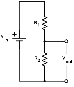
The size of the output voltage is given by
The ratio of the potential differences across each of the resistors is equal to the ratio of the resistances of the resistors.
Using a variable resistor
The potential divider can be used with a variable resistor across the output voltage, allowing to be easily adjusted.
Using a thermistor in a temperature control circuit
If a thermistor is used across the circuit can be used to control a heater on an on/off cycle.
Using a light-dependent resistor in an illumination control circuit
An LDR has a high resistance when the incident light intensity is very low. As the intensity of the falling light increases the resistance falls.
This means that the LDR can be used to switch lights on as the incident light decreases.
Internal resistance
Internal resistance The internal resistance of a source of e.m.f is the resistance to electric current of the materials inside a cell
Terminal p.d The potential difference recorded across the terminals of a cell.
Lost volts The difference between e.m.f and the terminal p.d when charge flows in a cell
So when no current flows, and
The e.m.f and internal resistance of a cell are constant values. It is therefore possible to have a situation in which different currents will flow for different load resistances.
The values can be solved using simultaneous equations.
Finding the internal resistance of a cell
I we rearrange and substitute for we have .
This equations has the form , so if we plot a graph of against we will have a straight line with negative gradient and positive intercepts.
The intercept will be equal to the e.m.f of the cell.
The gradient of the graph equals the internal resistance of the cell.
Circuit analysis
Analysis of series and parallel hybrid circuits
Many circuits have a parallel branch that is connected in series with other components.
It is helpful to calculate the resistance of the parallel network first, before adding it to the resistance of the other components that are connected in series with it.
Series circuits involving two sources of e.m.f
If two sources of e.m.f have opposite polarities the overall e.m.f can be found by taking one source to be the negative direction and summing them.
Parallel circuits involving two sources of e.m.f
The overall e.m.f available to the circuit can be found in the same manner as for a series circuit.
To calculate the combined effective resistance of the network, arrange as would normally be done for a parallel circuit.
Waves
Wave motion
Waves transfer energy from one place to another without any net transfer of matter.
Waves can be longitudinal or transverse.
In longitudinal waves the vibrations are parallel to the direction of energy transfer, resulting in the formation of compressions and rarefactions.
In transverse waves the vibrations are perpendicular to the direction of energy transfer.
Progressive waves Waves which transfer energy away from a source
Wave terminology
Wavelength The wavelength, of a wave is the distance between two successive identical points that have the same pattern of oscillation.
Period The period, , is the time taken for the wave to complete one pattern of oscillation
Frequency The frequency, , is the number of oscillations per unit time at any point. It is the inverse of the period of the wave
Displacement The displacement, , is the distance of any part of the wave from its mean position
Amplitude The amplitude, , is the maximum displacement that the wave reaches from its mean position
Phase difference The phase difference, , the difference in the pattern of vibration between two points in the wave. Two points that have exactly the same pattern of oscillation are said to be in phase, there is zero phase difference between them
Using an oscilloscope
An oscilloscope displays a voltage-time signal and can be used as a voltmeter to display and measure the output from a microphone or signal generator.
The frequency of a wave displayed on an oscilloscope can be determined if you know the settings of the time base on the oscilloscope.
This is the time taken for the luminous dot produced by the CRT to move a horizontal distance of 1cm across the oscilloscope’s screen.
Oscilloscope controls
Each horizontal division on the oscilloscope represents a unit of time. The time base control varies the seconds or milliseconds per division.
The uncertainty in the frequency measurement can be reduced by altering the time base such that one full wave has the widest possible range in the x direction.
If the time base is turned off, the spot no longer moves across the screen. This is useful for observing the intensity of the wave.
Each vertical division on the oscilloscope screen represents a unit of voltage. The sensitivity control varies the volts per division.
Wave speed and the wave equation
The wave equation
can also be applied to movement
In a time equal to one period, , the wave travels one wavelength, . Therefore the speed, , of the wave is
We know that the frequency is the reciprocal of the period, so this can also be written
Energy transfer by waves
A progressive wave transfers energy from one place to another. From a point source producing waves, this energy spreads out in all directions.
Intensity Power per unit area
The intensity is given by
If the power spreads out equally in all directions this can be written
Intensity and amplitude
The amplitude of a wave decreases as the wave spreads out from a source.
The energy of a wave is proportional to the square of its amplitude. Hence the intensity of a progressive wave is also proportional to the square of its amplitude. $I \propto A^2 $
Common properties of waves
Reflection
All waves can be reflected.
Ray A single line to illustrate the direction of a waves travel. Rays are always drawn at right angles to the wavefronts.
Refraction
Refraction occurs when a wave moves from one material into another.
In terms of refraction of light, we say that the two materials have different optical densities.
Two observations an be made when refraction occurs
- The wave will change its speed
- There may be a change in direction
Investigating refraction and reflection in a ripple tank
In a ripple tank, a motorised straight edge bar produces plane waves, while a small dipper produces circular waves.
When light is shone from above through the waves produced, the bright bands or curves of light seen on on the screen below the tank show the wave crests. This makes it possible to measure the wavelength of the water waves, and investigate the angles of reflection and refraction.
Reflection at plane and curved surfaces can be investigated, and the angles of incidence and reflection measured with respect to the normal.
A glass sheet is used to decrease the water depth and so produce a region with a different wave speed. The water level can also be adjusted.
If the separation of the wavefronts decreases this shows they are travelling more slowly. If the wavefronts are at non-zero angle when they cross the barrier, the waves also changes direction.
Diffraction
Diffraction The spreading out of a wave after passing around an obstacle or through a gap
Diffraction is most pronounced when the wavelength of the wave being diffracted is the same size as the gap that they are travelling through.
Interference
Interference The addition of two more more waves (superposition) that results in a new wave pattern
Electromagnetic waves
Common properties of electromagnetic waves
The electromagnetic spectrum has a range of values for wavelength of to .
Visible light is a small part of the electromagnetic spectrum ranging from approximately for violet to for red.
All electromagnetic waves share the following properties
- They can travel through a vacuum
- They possess both a magnetic wave and an electrical wave interlocked perpendicular to each other
- They travel at the speed of light in free space,
- They are all transverse waves
- They can all be reflected, refracted, and diffracted
- They can all demonstrate interference
- They can all be polarised
| Wavelength (m) | Frequency (Hz) | Method of production | Method of detection | Uses |
|---|---|---|---|---|
| to | to | Electrons oscillated by electric fields in aerials | Resonance in electronic circuits | TV, Radio, and telecommunications |
| to | to | Magnetron, klystron oscillators, using electrons to set up oscillations in a cavity | Heating effect, electronic circuits | Radar, mobile phones, microwave ovens, satellite navigation |
| to | to | Oscillation of molecules, from all objects at any temperature | Photographic film, thermopile, heating of skin | Heaters, night vision, remote controls |
| to | to | From high temperature solids, gases, and lasers | Photographic film, the retina | Sight, communication |
| to | to | From high temperature solids, gases, and lasers | Photographic film, phosphors, sunburn | Disco lights, tanning studios, counterfiet detection, detergents |
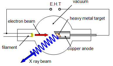
| to | to | Bombarding metals with high-energy electrons | Photographic film, fluorescence | Computer-aided tomography scans, X-ray photography, crystal structure analysis |
| to | to | Nuclear decay or in a nuclear accelerator | Photographic film, Geiger tube | Diagnosis and cancer treatment |
Non-ionising electromagnetic radiation
Radio waves, microwaves, and visible light do not have enough photon energy to remove electrons from the shells of atoms. For this reason they are deemed to be relatively safe.
Ionising electromagnetic radiation
Ultraviolet rays, X-rays, and gamma radiation all have high photon energies. This means that they can cause ionisation.
This can lead to human cell mutation and is therefore dangerous.
Ultraviolet radiation emitted by the Sun is often divided into three regions
- UV-A 315-400nm causes tanning when skin is exposed. Accounts for 99% of UV light
- UV-B 280-315nm causes damage such as sunburn and skin cancer
- UV-C 100-280nm filtered out by the atmosphere and doesn’t reach Earth
Production of X-Rays
Polarisation
Plane polarised wave A wave in which the oscillations of the field and the direction of travel are confined to a single plane
Polarising filter A filter which produces plane-polarised waves by selective absorption of one component of the incident oscillations.
Rotating the plane of polarisation
A second polariser called the analyser an be used to rotate the plane of the waves polarisation to a direction parallel to its long edge.
If the amplitude of the light wave approaching the analyser sheet is A, then after it has had its plane of polarisation rotated by angle the amplitude will be .
Because the intensity of a wave is proportional to its amplitude squared, the intensity after the analyser is proportional to .
This is know as Malus’ law.
It states that when a perfect polariser is put in a beam of polarised light, the intensity, , of the light that passes through it is given by , where is the intensity transmitted at angle .
Also is the maximum intensity transmitted (at ).
This law also shows that if the analyser is at right angles to the polariser no light will pass through. This situation is known as ‘crossed polaroids’.
Uses of polarisation
Polarisation can be used for strain analysis. Certain plastics, such as those used for making rulers, protractors and Sellotape, contain long chains of molecules which become aligned during manufacture.
These materials are able to rotate the plane of polarisation so that the transmitted light is polarised.
When these plastics are placed between two crossed polaroids, coloured images are produced that change as the plastics are stretched or squashed. This is because the rotation of the plane of polarisation is different for different wavelengths.
Refraction of light
For all types of electromagnetic radiation, the speed of the wave will decrease as it moves from a material of lower refractive index into a material of higher refractive index.
The speed of an electromagnetic wave in a material is related to the refractive index of the material by
A vacuum has a refractive index of 1, and air has a refractive index of 1.00028 ≈ 1.
Snell’s law
There is a link between the refractive indices of two materials and the directions at which the incident and refracted rays will travel with respect to the normal.
An electromagnetic wave travelling at an angle, , to the normal in a material, , will travel at an angle, , to the normal in a second material, .
This is explained by Snell’s law, which is given by
or that
The angle of incidence and the angle of refraction are always measured to the normal line, not to the boundary.
Total internal reflection
Total internal reflection The complete reflection of a light ray reaching an interface with a less dense medium when the angle of incidence exceeds the critical value.
The critical angle
In the specific case of total internal reflection between two materials, we know that is the refractive index of the material of higher refractive index.
is the sine of the critical angle.
The critical angle is given by
The ratio of to must be less than 1, so . The smaller refractive index must be .
Determining the critical angle for a transport material
To determine the critical angle of a material, use a semicircular shaped block of the material.
Draw around the shape on a piece of paper, making a mark at the centre of the straight edge and draw a normal at that point.
Shine a ray from a ray box towards the curved edge of the block in an arc until the ray emerges along the surface of the boundary between the material and air.
The angle the ray makes with the normal is the critical angle.
The critical angle can be used to find the refractive index of the material in question using
Interference
The principle of superposition
The principle of superposition states that when two or more waves of the same type meet, the resultant wave can be found by adding the displacements of the individual waves.
Interference
If two waves, A and B, with the same amplitude exist at the same point and are travelling in phase, the amplitude of the resultant wave will be twice that of the individual waves. This is constructive interference.
If the waves are in antiphase they will cancel each other out. This is destructive interference.
Coherence
Generally, waves will not be in perfect phase or antiphase.
So long as the two waves have a constant phase difference, they are coherent.
Path difference The path difference is the difference in metres between the lengths of two paths. It is often written in terms of the wavelength of two the wave
Phase difference The phase difference is the difference in radians of the phases of two waves of the same frequency
| Path difference | Phase difference | |
|---|---|---|
| Constructive | Integer number of wavelengths e.g. 0, λ, 2λ, … | 0, 360, 720, … or 0, 2π, 4π, … |
| Destructive | Odd number of half wavelengths e.g. λ/2, 3λ/2, … | 180, 540, 900, … or π, 3π, 5π… |
Interference using sound waves
Interference using sound waves can be demonstrated using two loudspeakers connected to the same signal generator. As you walk in front of the loudspeakers you will hear a loud sound where the sound waves reinforce one another, and a quiet sound where the waves partially cancel one another out.
This variation is clear if you cover one ear.
The distance between the loud and quiet regions is longer for lower frequencies.
The Young double-split experiment
The coloured patterns patterns seen on an oil spill on water are a result of the interference of light waves.
In order to make measurements of the wavelength of light, two conditions must be satisfied
- The light must be monochromatic
- There must be an accurate method of producing very small path differences, and of measuring these differences
The experiment
Light is produced by a monochromatic source and diffracts outwards, before reaching a second set of two narrow parallel slits.
The light from these two slits is coherent because it comes from a single slit.
When the waves reach an obstacle, alternate bright and dark vertical bands or ‘fringes’ will be seen.

For optimal results, the experiment should be carried out in a darkened room.
To reduce percentage error in the fringe separation it is best to measure across all the fringes and then divide by the number of fringes.
Increasing the distance from the slit to the screen will increase the fringe separation, but reduces light intensity at the screen.
Finding the wavelength of the light source
For constructive interference to take place, the path different must be a whole number of wavelengths.
For destructive interference to take place, the waves must arrive out of phase with path difference of half a wavelength.

In the diagram above, the two triangles are a similar shape, so their angles are equal.
If θ is the angle away from the central fringe
If the angle is small enough so
The equation only applies if , or the angle away from the fringe is less than 10°.
The diffraction grating
A diffraction grating is a piece of optical equipment made from glass, onto which many thousands of thin, parallel, and equally spaced grooves have been engraved using a diamond.
Light that passes through the grating will be diffracted at different angles based on the wavelength of the incident light and the separation of the grooves.
Multiple slits
It is difficult to accurately determine wavelengths using the Young double-slit experiment. The diffraction fringes are quite blurred, which makes measuring the fringe width difficult.
This can be overcome by using multiple slits.
Increasing the number of slits that the light has to pass through improves the brightness and sharpness of the maxima and makes it easier to measure an accurate value for the wavelength of light.
The maxima are also further apart, so the angle can be measured with a lower percentage uncertainty.
Because the length of n wavelengths, , must be equal to , we get the diffraction equation
where n is called the order of the maximum, is the wavelength of the incident monochromatic light, is the separation of the slits in the grating, and is the angle that the beam makes with the grating.
Measuring the wavelength of light using a diffraction grating

The wavelength is found using . If the grating has slits per metre the slit spacing, , is the reciprocal of this value.
The angle is found with a protractor. The percentage uncertainty in is decreased if is as large as possible. This occurs for smaller slit separations and also for higher order fringes, however the intensity of the higher order fringes is lower, making them difficult to locate.
could also be found geometrically, using , where is the distance from the central maxima and is the distance of the grating from the screen.
Stationary waves
It is possible to confine a wave, and its energy to a fixed position. These waves are called standing or stationary waves.
Examples include waves on strings, such as stringed instruments, and air columns in tubes or pipes.
Formation of stationary waves
Stationary waves are produced by interference in accordance with the principle of superposition.
In order for a stationary wave to be produced on a string or in a pipe, the two waves that overlap must be travelling in opposite directions, have the same frequency, and approximately equal amplitudes.
The process
- Initially there are two progressive waves moving in opposite directions
- The two waves are in antiphase, with a phase difference of 180° or π rad
- This leads to a resultant wave of amplitude zero
- As the waves move, they move into phase and they create constructive interference to produce a wave with an amplitude equal to the sum of the amplitudes of the individual waves
- The wave pattern for a whole cycle returns the waves to their original states
Node A node in a stationary wave is a point at which there is no displacement of the particles at any time
Antinode An antinode in a stationary wave is a point at which the displacement of the particles varies by the maximum amount
Stationary wave experiments
Stationary waves on strings
The frequency of vibration of a string is governed by
- Its mass per units length
- Its tension
- The length of the string
The effect of bowing a violin string is to create progressive transverse waves that travel in opposite directions along the string away from the bow. When these waves reach the points where the string is fixed to the body of the violin, they are reflected back along the string. They then interfere with each other producing a stationary wave.
A stationary wave in a guitar string obeys the equation
where
is the frequency of vibration ()
is the length of the string ()
is the tension in the string ()
is the mass per unit length of the string
Fundamental mode of vibration and harmonics
The simplest type of stationary wave on a string is a wave with a wavelength equal to twice the length of the string.
This type of oscillation is called the fundamental mode of vibration. The fundamental frequency is the lowest frequency, highest wavelength that can be produced on a string. However other notes of higher frequency can also be produced, and these are called harmonics.
The frequency of a harmonic is always an integer multiple of the fundamental frequency.

Stationary longitudinal waves
Stationary waves in closed tubes
A stationary longitudinal wave is a specific type of stationary wave, created by blowing across one end of a tube.
As with the stationary wave produced on a string, the stationary wave in the tube is produced when progressive waves travel in opposite directions through one another.
A progressive wave can be started at one end of a closed tube by blowing across the open end. This wave travels down the tube and is reflected at the closed end. This produces two progressive waves travelling in opposite directions, which then interfere to produce a stationary wave.
However, to produce a stationary wave the length of the tube must be such that a node is formed at the closed end, and an antinode at the open end.

Stationary waves in closed tubes
The sound wave will also be reflected at the open ends of a pipe. Since the tube is open at both ends, each end is an antinode.
Measuring the speed of sound in air
The speed of sound in air can be measured using a tuning fork and a tube of water.
The tube is held by a clamp and is movable so that its length can be altered. Because of the water in the measure cylinder, the tube is effectively closed at one end.
When a tuning fork of known frequency is struck and held at the open end, air molecules in the tube will vibrate and a stationary wave will be set up in the table.
By listening carefully, the fundamental frequency can be obtained, when the sound is loudest at the minimum length. This is achieved when the length of the tube is equal to one quarter .
The tube can then be lengthened by loosening the clamp, and the loudness of the sound will reduce initially before increasing again to a second maximum loudness when the length of the tube is equal to . The difference between these two lengths is equal to half the wavelength of the sound, , and the speed of sound can be determined by multiplying this value by two, and then by the frequency of the tuning fork.
Quantum physics
The photon
Quantum A small discrete unit of energy
Photon A quantum associated with electromagnetic radiation
Planck constant The Planck constant, , has a value of . Photon energies are always emitted in multiples of this value
The equation relating the speed of light, , the frequency of the wave, , and its wavelength, , is
or
Rearranging this equation and substituting gives an alternative equation for calculating the energy of a photon
Using LEDs to determine a value for the Planck constant
LEDs come in a range of colours. Because the colour or wavelength of the light being emitted is related to photon energy, we can use different LEDs to determine a value for the Planck constant.
We need the following equipment
- Four LEDs of different colours and known wavelenghts
- A DC power supply
- An ammeter and a voltmeter
- A resistor
The apparatus is set up with the LED, power supply, ammeter and resistor in series, and the voltmeter in parallel across the LED.
We can then measure the current flowing as we increase the p.d across the LED by adjusting the variable resistor. Obtain at least six values for and , in steps of over the range where the LED starts to emit light.
We then determine the activation voltage for each LED.
Using these values to plot a graph of activation voltage against the reciprocal of the respective wavelength, we achieve a graph with a gradient of
The energy of a photon is equal to the energy of the electrons that are excited in the semiconductor material of the LED
which can be rearranged to
Comparing this to the form of a straight line graph, we can see that is the gradient of the graph multiple by a constant
If we measure the gradient of the graph of activation voltage against the reciprocal of wavelength, and then multiply by the charge on an electron before dividing by the speed of light, we find a value for .
The electronvolt
Electronvolt The kinetic energy gained by an electron when it is accelerated through a potential difference of 1 volt
We calculate the energy gained by an electron using
or
The charge on an electron is and the potential difference is , so .
The photoelectric effect
When electromagnetic radiation of a particular frequency is shone on the surface of a metal, electrons are emitted from its surface.
This phenomenon is known as the photoelectric effect, and electrons that are released are called photoelectrons.
Demonstrating the photoelectric effect with a gold-leaf electroscope
The gold-leaf electroscope is composed of a brass stem to which a thin gold leaf is attached. There is a metal cap attached to the top of the stem and the metal to be irradiated with electromagnetic radiation is placed on the metal cap.
A metal plate (usually zinc is placed on the metal and is then charged negatively by touching it with a negatively charged polythene rod, or by electrostatic induction.
When this is done the metal stem and gold leaf will also become negatively charged, meaning that the stem and the leaf will repel each other.
It is also possible to make the zinc plate, metal stem, and the gold leaf positively charged.
Observations of the photoelectric effect
When visible light is incident on a positively charged metal plate, there is no movement of the gold leaf. The same is also true when UV light is shone on the positively charged plate.
Shining visible light on the negatively charged zinc plate also causes no movements in the gold leaf. No matter how bright or intense the visible light is, no movement of the gold leaf is observed.
However, when UV light is shone on the negatively charged zinc plate, the gold leaf falls.
This shows that the metal plate loses its negative charge through the emission of electrons, which are repelled by the negative charge on the electroscope. The discharge of the electroscope cannot be caused by ions in the air, because the electroscope is in a sealed vacuum.
Further experiments show that
- Electrons will be emitted from the surface of a metal only if the incident radiation is above a minimum frequency called the threshold frequency. This is determined by the metal itself. Below this frequency, no electrons are emitted.
- Emission of electrons starts the instant the surface starts to be irradiated, provided that the incident radiation exceeds the threshold frequency.
Threshold frequency The lowest frequency of radiation that will result in the emission of electrons from a particular metal surface
Explaining the photoelectric effect
The work function
In order for electrons to be released from the metal, the frequency of the incident radiation must exceed the threshold frequency. This is needed to provide at least the minimum energy required to release an electron from the surface.
Work function The work function of a metal is the minimum energy required to release an electron from its surface, overcoming the electrostatic attraction between the electron and the positive metal ions
When an incident photon collides with the metal
- If there is no emission of electrons
- If an electron is released, but it has zero kinetic energy
- an electron with is released from the metal surface
As the intensity of the radiation is increased, more electrons are released, but their kinetic energy does not increase.
Calculations with the photoelectric effect
Determining the maximum kinetic energy of photoelectrons
We can equate the work done to accelerate or decelerate charged particles with the kinetic energy transferred to the electrons
At the stopping potential, all the emitted electrons have been brought to rest, so we obtain a value for the maximum kinetic energy of the photoelectrons by multiplying the stopping potential by the charge on an electron, .
Rate of emission of electrons
- The number of emitted photoelectrons is directly proportional to the intensity of the incident radiation, provided that the radiation is of a single frequency and is above the threshold frequency
- The kinetic energy of the emitted photoelectrons is not affected by the intensity of the incident radiation
- The kinetic energy of the emitted photoelectrons is affected by the frequency of the incident photons. If the frequency of the incident radiation is increased, the kinetic energy of the photoelectrons also increases
Millikan’s photoelectric experiment
Millikan irradiated the metals sodium, potassium, and lithium with monochromatic light. By applying a positive potential to the target metal, he could decelerate the electrons.
He increased the size of the potential until the most energetic electrons were unable to reach the cathode, causing the current to fall to zero.
This enabled him to determine the stopping potential, , of each metal, and show that this depends on the frequency of the radiation.
Not only did Millikan’s experiment obtain accurate values for the work functions of the metals, it also obtained an accurate value for Planck’s constant.
We know that
and
If we divide both sides by the electron charge, e, and rearrange for we have
This equation is of the form , meaning that if we plot a graph of stopping potential, , against frequency, , we will have a graph of gradient over , and a intercept equal to .
If we measure the gradient and multiply it by , we get a value for Planck’s constant.
If we read the intercept and multiply by , we get a value for the work function of the metal.
Wave particle duality
The wavelength of electrons
De Broglie proposed that if electrons and other particles travel through space as a wave, they have an associated wavelength. By combining the idea of an energy quantum with he derived a formula for the wavelength, , of a particle
where is the mass of the particle, and h is the Planck constant.
This equation was confirmed by observing the behaviour of electrons that had been diffracted from the surface of a nickel crystal.
By accelerating electrons, of charge e, through a potential difference , they observed a pattern of electron diffraction from which they could calculate the electron’s wavelength.
The predicted wavelength is found by equating the work done to accelerate the electrons with the kinetic energy transferred into the electrons
Substituting
into the de Broglie equation gives

Wave-particle duality for matter
The experiment confirming De Broglie’s results shows that matter could exhibit wave properties. According to De Broglie’s equation, all moving objects have a wavelength, including solids.
The greater the mass of the object, the shorter the wavelength, and macroscopic objects have such small wavelengths that their effects are negligible.
In modern physics, the wave nature of a particle is considered a probability wave. It represents the probability of an observer measuring a particle at a given place and time.
Newtonian World and Astrophysics
Thermal physics
Temperature
Kinetic model of matter A model allowing us to explain the properties of matter and changes of phase in terms of the arrangement of the particles, their motion, and the attractive forces between them
Atomic or molecular spacing
The density of any substance in kilograms per metre cubed is given by
density () mass of one molecule ) number of molecules per cubic metre ()
The mass of one molecule of water is the same for all three phases, so the density is directly proportional to the number of molecules per cubic metre.
Assume that the molecules behave like small spheres.
Placing them in a cube of volume 1 metre cubed.
If the distance between is , then the number along one edge is and the number in the entire box is .
More generally, suppose there is a volume of a substance composed of molecules.
We have
Example
of copper contains atoms of copper. Copper has a density of at room temperature.
Estimate:
The number of copper atoms present in of copper
The number of copper atoms present in of copper
The diameter of a copper atom
Using the previous answer we have giving and finally
Change of phase
Changing phase requires either an input of energy of a removal of energy.
Heating a solid will cause it to melt and become a liquid. Further heating of the liquid will cause it to evaporate and become a gas.
This is due to the energy of the particles increasing as energy is supplied. The extra energy results in the particles moving further and further apart until they have enough energy to overcome the forces of attraction to their adjacent particles.
Conversely, removing thermal energy from a system will reduce the energy of the particles causing them to move closer together, leading to condensation and freezing.
Internal energy
Internal energy the sum of the randomly distributed kinetic and potential energies of all the atoms or molecules within a system
The kinetic energy of the system is due to the movement of the particles within the system.
The potential energy of the system is stored in the bonds and inter-molecular forces that exist between the particles.
This stored energy will be released when the attractive forces between particles are overcome, such as during melting or evaporating.
Internal energies for solids and liquids
In solids, the particles’ kinetic energy is usually in the form of vibrational motion as the particles each oscillate about their respective equilibrium separations. This gives varying kinetic energy.
The total internal energy is the sum of all the kinetic and potential energies within the solid.
Two uncharged atoms exert forces on each other due to the repulsive forces between their electron clouds and the attraction between the protons of each atom and the electrons of the other.
At the equilibrium separation, , the attractive and repulsive forces are exactly in balance.
For spaces closer than the equilibrium separation, the atoms repel each other, and for spaces larger than this the atoms attract.
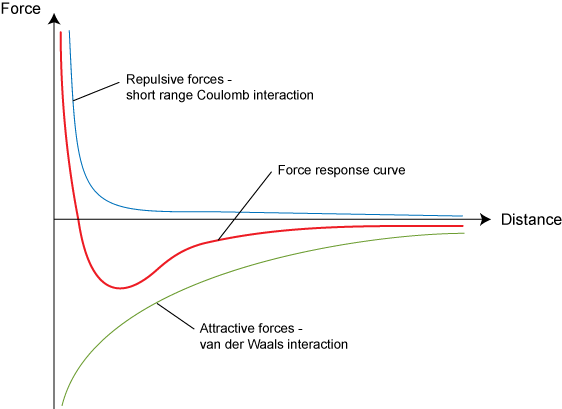
The equilibrium separation represents the minimum potential energy, and is therefore the preferred separation of the solid.
As the temperature of a solid or liquid increases, the kinetic energy of the atoms or molecules present within the system increases as the vibrations increase in amplitude. Potential energy will also increase slightly as the mean separation between the atoms increases slightly.
Internal energy for a gas
Particles in a gas are able to move freely, and the particles’ kinetic energy therefore takes the form of translational motion.
The particles move randomly with different speeds and directions inside their confined space, bounding off each other and the walls of their container as they do so.
The motion of the atoms or molecules gives them enough kinetic energy to move far apart.
As the separation increases, the force between the two atoms or molecules decreases.
The effect of intermolecular forces is small (zero for an ideal gas). This means that the potential energy component of the internal energy of a gas is very small.
If any system of gas particles is at a fixed temperature, there will be a distribution of kinetic energies among the molecules.
The Maxwell-Boltzmann distribution models this.

Internal energy during change of phase
When a material changes phase, it does not undergo any change in temperature. Therefore, the kinetic energy component of the internal energy does not change.
The potential energy, however, does change.
Brownian motion
Brownian motion The random movement of small visible particles suspended in a fluid due to collisions with much smaller, randomly moving atoms or molecules of the fluid
Brownian motion was first observed in 1827 by Robert Brown when he observed the motion of pollen particles in water.
Brownian motion can be observed with a microscope and a focused filament lamp.
In accordance with the kinetic model of matter, all particles above absolute zero in temperature are in constant motion. The movement cannot however be accurately predicted as there are so many particles moving.
Pattern of movement of solids, liquids, and gases
When a solid is heated it will experience a rise in temperature, and the kinetic energy of its particles will increase. As the material is solid, the position of each atom, ion, or molecule will not change, since the particles are held in place by interatomic or intermolecular forces.
The increase in kinetic energy will result in greater vibration of the particles in the solid around their respective equilibrium positions.
In a liquid, the same effect takes place. This time, a small amount of translational kinetic energy will be added to the increase in vibrational kinetic energy, since the molecules are now ale to move past one another from place to place.
In a gas, almost all of the kinetic energy is translational as the particles move from place to place,.
Aerosols
The smell of a perfume or air freshener quickly moves across a room. This movement, called diffusion, is not Brownian motion but instead convection.
Specific heat capacity
Specific heat capacity The specific heat capacity, , of a substance is the amount of energy needed to raise the temperature of of the substance by . ()
When energy is supplied to a body of mass by heating, the kinetic energy of its particles will increase and its temperature will rise.
The amount that the temperature increases or decreases is proportional to the mass of the object, the specific heat capacity of the object, and the energy supplied.
where
- is the change in thermal energy ()
- is the mass of the body ()
- is the specific heat capacity of the object ()
- is the change in temperature ( or )
Example
The specific heat capacity of aluminium is
How much energy is needed to raise the temperature of of aluminium from to ?()
Determining the specific heat capacity of a material
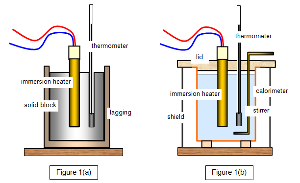
- Insulate the material being heated and use a lid for liquids to ensure that as much as possible of the thermal energy supplied to the system is used to increase the temperature of the material. The temperature change should be as high as possible, , so as to reduce percentage uncertainty.
- Use an ammeter and voltmeter in the heating circuit to determine the power.
- Heat the material for a given time, until the required temperature change has been reached, and then calculate the energy expended with .
- Assuming that all of the energy transferred electrically is used to heat the material, use the principle of conservation of energy to give .
Specific latent heat
Specific latent heat of fusion () The amount of energy required to change the phase of of a substance from a solid to a liquid
Specific latent heat of vaporisation () The amount of energy required to change the phase of of a substance from a liquid to a gas
Changing phase
In order for a material to change phase from a solid to a liquid, or from a liquid to a gas, forces of attraction between atoms or ions in the material must be overcome.
In order to separate the particles, work must be done on the material.
The energy required to cause a change of phase is called the latent (hidden) heat.
Changes in temperature during phase changes
Experiments show that there is no change in temperature for some time at both the melting and the boiling point of a material, even thought thermal energy is being supplied.
When a substance changes phase the temperature remains constant so there is no increase in the kinetic energy of the atoms or molecules. The internal energy, however, does change, this is because a change in the forces between molecules during a change in phase produces a change in their potential energy.
Specific latent heat of fusion
When a substance is at its melting point, the energy required to change the phase of the substance from a solid to a liquid, or a liquid to a solid, is called the specific latent heat of fusion ().
The energy is taken in by the substance when it melts and given out by the substance when it freezes.
The term specific refers to the specific mass of from which the latent heat can be found for any mass.
The latent heat for a mass () is given by
Example
Given that the specific latent heat of fusion of water is , determine how much energy is required to convert of ice into liquid water.
Determining the specific latent heat of fusion

A known mass of ice is placed into two funnels, A and B.
The heater in arrangement A is connected to a power supply of known power P.
The control, B, is not connected to a power supply.
When water starts to drip from the funnels, the heater is switched on.
After 15 minutes the heater is switched off and the mass of the water in both beakers is measured.
The mass of the water in beaker B is the control value, which is to be subtracted from that of A to account for enegy accrued from the surroundings.
We then have that
Specific latent heat of vaporisation
When a substance boils or condenses, the specific latent heat of vaporisation () is the amount of energy required to change the phase of of the substance from a liquid to a gas or vice versa.
Determining the specific latent heat of vaporisation
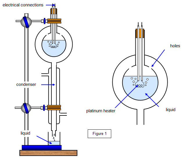
The liquid whose specific latent heat of vaporisation is to be determined is heated to boiling point.
The vapour that is produced passes through the holes and into the condenser.
The vapour is collected for a time, , and its mass, , is determined.
At this point the current in the circuit is and the potential difference across the heating coil is .
By equating electrical energy supplied to thermal energy transferred we have where is the thermal energy transferred to the surroundings in time .
The potential difference across the heater and the current flowing through the heater are now changed to new values and respectively.
The mass of water vapour that is produced in the same time, , as before is noted and called .
This leads to .
The value of will be the same in each case, since the temperature of the apparatus has not changed.
Subtracting the two equations, we can eliminate , to give .
Since we know know the values, the specific latent heat of vaporisation is given by
The amount of substance
Moles
It is more useful to use the SI unit for the amount of a substance than to simply count the number of molecules in the substance.
One mole of any substance is the amount of the substance which contains as many atoms, molecules, or ions as there are atoms in of carbon-12.
The mass of one mole of a substance is called the molar mass.
The molar mass of a substance in grams is determined by its relative atomic mass, or the molecular mass, multiplied by the number of particles in one mole.
This number is the Avogadro constant
Molar mass of monatomic gases
Monatomic gases are composed of single atoms, such as helium. The mass of one mole of a monatomic gas is equal to its relative atomic mass.
Molar mas for diatomic gases
Nitrogen and oxygen are diatomic. Nitrogen and oxygen gas exist as molecules, each containing two atoms.
Nitrogen has a relative atomic mass of 14, and that of oxygen is 16.
Since they are diatomic, a mole of nitrogen gas () will have a mass of and a mole of oxygen gas () will have a mass of .
The relationship between Avogadro’s number (), the number of moles (), and the number of particles ()
One mole of a substance contains particles
moles of a substance contain particles
The number of particles present in a gas is equal to the number of moles multiplied by Avogadro’s number.
Example
Calculate:
a) The number of atoms in 3 moles of copperatoms
b) The mass of 3 moles of copper
Mass of mole is
Mass of moles =c) The number of atoms in 5 moles of neon gas
atoms
d) The number of molecules in 5 moles of oxygen gas
molecules
e) The number of atoms in 5 moles of oxygen gas
atoms
The kinetic theory of pressure of a gas
Ideal gas A gas that has internal energy only in the form of random kinetic energy
Mean square speed The mean value of the square of the velocity, , for a large number of gas particles moving randomly in a gas
Root mean square speed The square root of the mean square speed
Assumptions of the kinetic model of gas
- The gas contains a large number of particles
- The particles move rapidly and randomly
- All collisions are perfectly elastic, conserving kinetic energy
- There are negligible attractive forces between particles during collisions
- The time for a collision to happen is negligible compared to the time between collisions
- Particles have a negligible volume compared with the volume of gas in the container
Ideal and real gases
In reality the forces between the particles in a gas are not negligible and cannot be ignored. However, real gases will behave like ideal gases if they are at low pressure and a temperature significantly above their boiling point.
The internal energy of an ideal gas is composed entirely of the kinetic energy of its fast-moving particles, since we assume that there are no inter-molecular forces that could lead to additional potential energy in the system.
Pressure of gases
A gas in a container exerts pressure on the container walls due to collisions of gas molecules with the container walls.
Pressure is a vector quantity, since it has both a magnitude and a direction.
Pressure is defined as the force, , acting perpendicular to an area, . () ().
Gases are likely to have large numerical values of pressure because gas molecules may be travelling fast and there are huge numbers of them.
Atmospheric pressure is approximately , the reason that objects are not crushed under this pressure is that there are equal and opposite forces acting outwards.
Using the kinetic theory to obtain an equation for the pressure of an ideal gas
Suppose there are three molecules moving in a cubic box of side length . The molecules each have mass and are travelling at speed parallel to each of the axis respectively.
Let us consider only the first molecule, travelling parallel to the axis, and one wall of the box.
When the molecule hits the wall, it will rebound with velocity since since all collisions with the wall are perfectly elastic.
Initially, the momentum of the molecule is . Having collided with the wall and rebounded, its momentum will become , giving a change in momentum of .
The molecule will collide with the wall again after it has travelled a distance of across the box and back to the same wall.
The time it takes to do this is
By Newton’s second law of motion, the force, , exerted on the wall will be equal to the rate of change of momentum, so we have
From Newton’s third law, the molecule exerts an equal and opposite force on the wall.
The pressure on the wall is given by force over area, which in this case is .
Since the box is a cube, we can replace with the term to denote the volume, giving .
If there are gas molecules in the box the total pressure exerted on the wall will be given by the sum of the individual forces acting on the area of that wall.
In reality, the molecules move randomly in all directions, not in one direction as is modelled here.
Only changes of momentum in the direction perpendicular to the wall will cause an impact force on the wall.
For molecules travelling in the direction, the pressure exerted on the wall will be given by
This can be related to the mean value of the square of the component in the direction, , where
The pressure on one wall is then given by
Finally we must consider the motion of all the molecules that have components of velocity in the and axes.
If the velocity of a gas molecule is which can be resolved into components of and , it can be shown that
From the assumption of kinetic theory, the velocity is in a random direction, so the mean velocity component will be equal in every direction and . Hence it is possible to say that .
The total pressure is then , which can also be written
Alternatively, since the total mass of the gas is and since the density, , of the gas is , we obtain an expression for the pressure of an ideal gas as .
Investigating gases
Boyle’s law The volume of a fixed mass of gas is inversely proportional to the pressure exerted on the gas, under conditions of constant temperature.
If we have a gas at a pressure and volume , and we then change the conditions so that the gas has a new pressure and a new volume we can then say that .
Investigating Boyle’s law
Boyle’s law can be demonstrated with a measuring tube closed at one end and containing air above some oil.
The pressure on the oil can be increased by a foot pump, and the volume of air in the measuring tube can then be re-measured.
The values of pressure against volume once recorded can be plotted on a graph of against to give a linear plot, demonstrating the inverse proportionality.
The pressure temperature The pressure of a gas under conditions of constant volume is proportional to the absolute temperature of the gas.
Investigating pressure and temperature of a gas at constant volume

A fixed mass of a gas is heated in a sealed flask at constant volume.
The flask is placed in a water bath which is then heated to different temperatures and the pressure of the gas at each temperature is recorded.
When a graph of pressure against temperature is plotted, it will be linear with an intercept on the temperature axis of .
The ideal gas equation
Equation of state of an ideal gas The pressure of a gas, , with a volume, , when multiplied are equal to the molar gas constant, multiplied by the number of moles of gas, , and the temperature of the gas, .
Boyle’s law
Charles’ law
The pressure-temperature law
Collectively, these laws are called the gas laws.
The laws apply to most gases, but break down if the gas is close to its boiling point or at a very high pressure.
The laws also only hold for temperature values expressed in kelvin.
The ideal gas equation
In an ideal gas, there are no intermolecular forces between the gas atoms or molecules. An ideal gas will obey the gas laws exactly.
By combining the three gas laws we obtain for a fixed mass of gas.
The constant is dependent on the amount of gas present, the number of moles, . Introducing the molar gas constant, , we obtain , where .
For ideal gases which change their conditions of pressure, volume, or temperature, the equation can also be written as .
Example
A piston contains of gas at a pressure of and a temperature of .
The gas is then compressed to a new volume of under a pressure of .
What is the new temperature of the gas?
As the units are constant, the values can be inserted straight into the equation.
The Boltzmann constant
Boltzmann constant () A constant which relates the temperature of a gas to the mean translational kinetic energy of the particles in the gas. It can also be regarded as the gas constant for a single molecule.
Example
Neon is a monatomic gas with a molar mass of . If it is kept in a cylinder of volume at a pressure of and a temperature of , find:
a) The number of moles of neon in the cylinder
Substituting the values gives
molesb) The mass of neon in the cylinder
Mass of neon = number of moles x mass of one mole
c) The number of atoms of neon in the cylinder
Neon is monatomic, so there are atoms for each mole of neon
The Boltzmann constant
When dealing with a system containing a certain number of atoms or molecules, as opposed to moles, we use the Boltzmann constant, . The Boltzmann constant is related to the molar gas constant in that .
The state equation for an ideal gas can then be adapted, so that for moles we have and for atoms or molecules we instead have .
Example
Neon gas is kept in a metal bottle at a pressure of and a volume of .
The gas is in thermal equilibrium with its surroundings at a temperature of .
Calculate:
a) The number of atoms of neon in a metal bottle
Substituting the given values we have
b) The number of moles of neon present
The relationship between the absolute temperature and the kinetic energy of a gas molecule
We know that
Factorising the left hand side gives
Further manipulation gives
Since , we obtain
This shows the relationship between the mean kinetic energy of a molecule of mass, , the mean square speed, , and the absolute temperature, , of an ideal gas.
It also shows that mean kinetic energy is directly proportional to absolute temperature for a molecule, and constant at a given temperature.
For an ideal gas, all the internal energy is in the form of kinetic energy, so its internal energy is also proportional to absolute temperature.
Example
Calculate the average speed of a nitrogen molecule at a temperature of
if the mass of a nitrogen molecule is .
Substituting the given values gives
Taking the root of we have
Example 2
What temperature would of helium gas be if its internal energy was equal to the kinetic energy possessed by a rubber ball that was moving at ? (R.A.M of Helium is )
The total kinetic energy of the system is equal to
This energy is distributed throughout of a mole of helium, meaning that the number of helium atoms present is .
We then have
Giving a
Circular motion
Kinematics of circular motion
Radian The angle subtended at the centre of a circle when the arc is equal to in length to the radius of the circle
Period The period is the time taken in seconds for one complete circular path
Angular velocity () The angular velocity is the rate of angular rotation, measured in radians per second
Centripetal acceleration The centripetal acceleration of an object moving with uniform circular motion. The magnitude of the acceleration is given by where is the speed of the object and is the radius of the circle, or where is the angular velocity
The centripetal acceleration is directed radially inwards towards the centre of the circle, perpendicular to the velocity vector at any instant.
Example
A body, moving in a circular path of radius , covers an arc length of in . Calculate:
a) The size of the centripetal acceleration
can be found by dividing the arc length by the time taken
b) The angle swept out in radians in this time
c) The angular velocity
d) The time period
Centripetal force
Centripetal force The resultant force on an object, acting towards the centre of the circle, causing the object to move in a circular path
The centripetal force is given by
Circular motion and Newton’s laws
When a body moves in a circular path, it is subject to Newton’s three laws of motion.
Since the body is travelling in a circular path, its direction must be constantly changing even though it may be rotating at a constant speed.
This means that the body will be constantly accelerating.
Both the centripetal force and the centripetal acceleration act radially inwards, towards the centre of the circular path.
Example
The moon has a mass of and orbits the Earth with a speed of . If the distance from the Earth to the centre of the moon is find the value of the centripetal force, stating the origin and direction of the force.
This force acts towards the Earth.
Example
A fan blade of radius and mass rotates with an angular velocity of What is the size of the centripetal force acting on the blade?
Gravitation and the centripetal force
Investigation
Investigating circular motion using a whirling bung
Centripetal force can be investigated using an object being whirled in a horizontal circle.
The diagram above shows an arrangement which can be used.
- Tie one end of the thread to a rubber bung and make a mark on the string at a distance of from the bung
- Attach a weight at the other end of the string and whirl the rubber bung in a horizontal circle
- Adjust the speed of rotation such that the radius, , of the circle is constant and equal to , and then continue to whirl the bung at a constant speed
- Measure the time, , for revolutions of the bung
- Determine the speed, , of the bung using
- Repeat the experiment for different values of the centripetal force, , by adding masses to the bottom of the string and adjusting the speed of rotation until the bung whirls in a circle of the same radius as before
- Plot a graph of force, , against ,. Draw a straight line of best fit, which will have gradient
- Determine the mass of the bung from the gradient and the value of used in the investigation
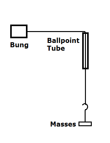
The conical pendulum
A ball swinging from a conical pendulum is in equilibrium vertically, but there is a resultant fore on the ball directed horizontally towards the point below the vertical.
The vertical component of the force must be equal and opposite to the weight of the ball, and the horizontal component must accelerate the ball towards the center of its motion in its horizontal plane.
The two equations can be used to show that
Motion in a vertical circle
At the top of a vertical pendulum, there is already a downward force acting on the swinging object, the centripetal force is then .
At the bottom the weight of the person acts in the opposite direction to the centripetal acceleration. The resultant force is then .
Oscillations
Simple harmonic motion is oscillatory motion such that the acceleration, , of the oscillating body is directly proportional to the displacement, , of the body from its equilibrium position and is always directed towards that point.
The magnitude of the acceleration increases as the displacement increases. Acceleration is maximum when the displacement, , is maximum at .
The constant of the equation can be written in terms of the frequency, , or angular frequency, , of the oscillations giving
Velocity and acceleration in simple harmonic motion
The velocity of a body undergoing simple harmonic motion is given by
The values for the maximum velocity is then given by , and further
Example
A simple pendulum bob is displaced from its equilibrium position so that it has an amplitude of . It is then released and allowed to perform oscillations. The total time to complete these oscillations is timed as .
Calculate:
a) The time period of oscillation of the pendulum
b) The frequency of oscillation of the pendulum
c) The acceleration of the pendulum when it is from its equilibrium point
d) The velocity of the pendulum bob when it is from its equilibrium point
e) The maximum acceleration of the pendulum bob
f) The maximum velocity of the pendulum bob
The solution to
The two solutions are and , where is the time in seconds since the oscillatory motion began.
These equations satisfy the following characteristics of simple harmonic motion:
- Velocity changes smoothly and is symmetric around the equilibrium position
- Velocity at maximum displacement is zero
- Maximum acceleration occurs at the maximum displacement
- Maximum velocity occurs at the equilibrium position
The two solutions are out of phase with each other by radians. This allows us to use when the timing of the simple harmonic motion starts from the point where the pendulum is released at its maximum displacement. is used to describe the motion of the pendulum body when it starts such that the displacement is 0 at .
Example
A pendulum is released from its highest point, at which point the timer is started. The original displacement of the pendulum from its equilibrium point is and its time period is . Calculate:
a) The frequency of the oscillation
b) Its displacement when
Graphical analysis of simple harmonic motion
Isochronous Motion with a period that is constant and independent of of the amplitude of the oscillation
Acceleration displacement graph for simple harmonic motion
The acceleration displacement graph is a straight line of negative gradient for simple harmonic motion. The acceleration is always proportional to the negative of the displacement.
Energy of a simple harmonic oscillation
Energy interchanges during simple harmonic motion
During one complete oscillation of a body performing simple harmonic motion, the interchange of energy between kinetic and potential energy follows a quadratic curve.
Energy changes for a mass on a spring
The total energy of the system must remain constant while the mass oscillates. Any gain in kinetic energy is balanced by a loss in potential energy, however there are two types of potential energy which must be considered. The spring gains elastic potential energy when it is extended and the mass gains gravitational potential energy when it rises.
The elastic potential energy stored by a spring when stretched by a distance is given by . The gravitational potential energy stored when an object rises a distance is given by .
Damping
Damping Damping forces reduce the amplitude of an oscillation with time, due to energy being removed from the oscillating system
Uses of damping
Damping affects the rate of decay of vibrations.
Damping can occur in oscillations due to the effect of air resistance or other frictional forces, this is referred to as natural damping.
The process of deliberately reducing the amplitude of an oscillation is called artificial damping, and it is used to ensure that the amplitude of vibrations dies down quickly.
In a car’s shock absorber energy is removed from the system by dissipation through the hydraulic fluid as it is compressed.
Effects of damping
If only small damping forces exist, which is known as light damping, the period of the oscillation is almost unchanged, but the amplitude of the oscillation will gradually decrease.
As the damping force increases, rate at which the energy is removed from the system increases, there is a more noticeable reduction in amplitude and the period of oscillation will decrease slightly.
In the case of very heavy damping, no oscillation occurs, and the body slowly moves back to its equilibrium position.
Critical damping Damping which provides the quickest approach to zero amplitude for a damped oscillator
Example
State and describe the nature of the damping that takes place in the following
a) A playground swing that continues to oscillate backwards and forwards for minutes once a child has jumped from the moving swing
Light natural damping is observed as the frictional forces are low in magnitude and occur as a result of air resistance and friction in the support
b) A test tube that bobs up and down in water for a few seconds before coming to rest
This is heavier, artificial damping being observed since the oscillations die quickly due to the deliberate use of water
c) A test tube that oscillates in treacle for less than one oscillation before stopping
This is very heavy damping, which in this case can also be referred to as critical damping because there is no oscillation occurring
Resonance
Natural frequency The frequency at which a system will oscillate when no external force is acting
Free oscillations Free oscillations occur when there is no external periodic force. The system oscillates at its natural frequency
Forced oscillations Forced oscillations occur when an external force or driving force is applied to keep the body oscillating. The system oscillates at the frequency of the driving force
Driving frequency The frequency of the driving force applied to an oscillating object
Resonance Resonance occurs in a forced oscillation when the driving frequency is equal to the natural frequency of the system being forced to oscillate. This results in the body oscillating at its natural frequency and maximum amplitude
| Free oscillations | Forced oscillations |
|---|---|
| A pendulum swinging | An object being pushed on a swing |
| A mass-spring system | A building vibrating during an earthquake |
| An object bobbing on the surface of water | The beating of a bird’s wings |
Barton’s pendulums

In the figure above, a heavy mass is pulled in the axis perpendicular in the horizontal to the bar. Once released, the heavy mass will perform free oscillations and oscillate at its natural frequency.
As the heavy mass swings backwards and forwards, energy is transferred along the string to the other pendulums which will also start to swing in the same plane.
Since the length of the pendulum determines its natural frequency, the pendulum of the same length as the driver pendulum will oscillate at its natural frequency.
The phase difference between the oscillation of the driver pendulum and the driven pendulum will be rad.
Practical uses and dangers of resonance
There are many practical and useful applications of resonance. These include the tuning circuits that respond to a particular radio or TV frequency, microwave ovens cooking food due to the resonance of water molecules at a particular frequency, and the timing mechanisms of some clocks which are controlled by the resonant vibrations of quartz crystals.
Conversely, resonance can have dangerous consequences.
Care must be taken to eliminate unwanted vibrations at a resonant frequency.
A combination of damping to quickly reduce the amplitude of vibrations at the natural frequency and careful choice of the dimensions of an object is used.
Gravitational fields
Gravitational field The region around a body in which other bodies will feel a force due to the mass of the body
Gravitational field lines Lines which how the shape of the field. The direction of the field line at a point is the direction in which a small mass would move when placed at that point
Gravitational field strength At any point in a gravitational field the gravitational field strength is the force acting per unit mass at that point,
The Earth’s gravitational field
The field lines are always directed along a radius towards the centre of the Earth
The gravitational field is stronger when the lines are closer together
The field lines are radial in nature. The distance between two field lines at a distance twice as far away from the centre will be twice as large as that at the original distance from the centre.
As the distance from a mass to a point in space increases by a factor of the gravitational field strength decreases by a factor of .
Over short distances at the surface of the Earth, there is very little variation in the gravitational field strength. The field is said to be uniform over short distances, this would appear as parallel field lines over a short range.
It is only over a large distance from the Earth’s surface that the field lines diverge and we observe the radial nature of the field.
Calculating gravitational field strength
The gravitational field strength of the Earth varies at the surface of the Earth because matter is not uniformly distributed across the Earth and so the gravitational force can vary slightly.
The relationship between acceleration due to gravity and the gravitational field strength
For a mass near the Earth’s surface the gravitational field strength is given by .
We also know that in free fall the acceleration of a mass when acted on by its weight has the values , so the weight of a mass if .
This gives the gravitational field strength of the Earth at its surface to be .
Newton’s law of gravitation
Two bodies that have mass will attract one another with a force that is directly proportional to the product of their masses and inversely proportional to the square of their separation.
where and are the masses of the two bodies and is the separation of their centres.
is the universal gravitational constant and has a value of .
Point and spherical masses
Newton’s law of gravitation is stated for two point masses. However, a spherically symmetric mass can be considered to be a point mass, as if all of its mass were concentrated at its centre.
Gravitational field lines act radially towards the centre for both a point and a spherical mass.
Gravitational field strength,
For a body of mass placed in the radial field of a spherical or point object, the size of the gravitational force is found at any point by using Newton’s law of gravitation.
It follows that
Example
The Earth has a mass of and a radius of . If the value of the gravitational constant, , is
, then:
a) Calculate the value of at the surface of the Earth
Using we have
b) Calculate the value of at the surface of the Earth if the measured weight of a man of mass is .
c) Comment on the values obtained in a and b
The values are very similar as expected. The slight difference is due to the valued used in fin the radial equation as this may change over the Earth due to it not being perfectly spherical. also varies over the surface of the Earth due to uneven distribution of mass in regional geological structures.
Variation of from the Earth’s surface outwards
Moving away from the Earth’s surface by a distance , the gravitational field strength will then be given by .
The motion of planets and satellites
Kepler’s third law The square of the period of a planet orbiting the Sun is proportional to the mean radius of its orbit cubed. . Kepler’s law also applies to other planetary systems, such as to the orbits of moons around planets
Geostationary orbit An orbit of the Earth made by a satellite that has the time period and orbital direction as the rotation of the Earth and is in the equatorial plane
Kepler’s laws of planetary motion
Kepler’s first law All planets move in elliptical orbits, with the Sun at the mutual foci
Kepler’s second law A line that connects a planet to the Sun sweeps out equal areas in equal times
Kepler’s third law The square of the period of any planet is proportional to the cube of the radius
For bodies that move in a circular path, this becomes
Kepler’s third law is an empirical law because it was based on available data without being based on any scientific theory or hypothesis.
It could not be explained until Newton’s laws of gravitation.
The sun and its satellites actually orbit a common centre of mass, called the barycentre.
Kepler’s second law means that orbiting bodies much accelerate as the distance to their focus decreases.
Using Newton’s law of gravitation
Equating this to the net centripetal force we have
We then have
Finally
A satellite of mass kg is at a height of m above the surface of the earth.
Calculate the gravitational force of the Earth attracting the satellite. The satellite is in a circular polar orbit.
Show that the satellite would travel around the Earth three times
every 24 hours. State and explain one possible use for the satellite
travelling in this orbit.The orbital period T is
Gravitation and orbits
Newton found that the force of gravitational attraction between two bodies is given by
By equating the gravitational force to either of the equations for the centripetal force required to keep a body of mass around a body of larger mass , we have
Substituting into the second equation above gives
Example
The Earth has a mass of and the Sun has a mass of . The Earth orbits the Sun with an orbital radius of .
By equating the centripetal force and the force of gravitation, determine:a) The speed of the Earth as it travels in its orbit around the Sun
Using we can make the subject
b) The time taken for the Earth to orbit the Sun once
Using we can make the subject
As we then have .
We can also derive Kepler’s third law from Newton’s law of gravitation.
For a planet orbiting the sun where is the velocity of the planet’s motion, we have and using for the centripetal acceleration we then have
Leading to
Example
Two of Jupiter’s moons are called Io and Europa. Europa has an orbital period of approximately and orbital radius of , Io has an orbital period of .
What is the size of Io’s orbital radius?Since for a body in circular motion around a mass , the ratio can be equated for any two bodies in orbit around the same mass.
We set
Rearranging this gives
Geostationary satellites
Geostationary orbit An orbit with a period equal to that of the period of rotation of the Earth, such that the satellite remains at the same point relative to a stationary observer on the Earth
Geostationary satellites are used for
- Broadcasting TV signals and relaying mobile phone signals
- Monitoring the weather and changes in the environment
- Monitoring air traffic
The radius for geostationary orbit can be found by Kepler’s third law
Substituting our values gives
If we subtract the radius of the Earth , we find the height that a geostationary satellite must be placed above the Earth’s surface, which is approximately .
Gravitational potential and gravitational potential energy
Gravitational potential The gravitational potential at a point in a gravitational field is defined as the work done in moving unit mass from infinity to that point
Gravitational potential energy The gravitational potential energy of a mass in a gravitational field depends on its position in the field. For a radial field around a point or or spherical mass , the gravitational potential energy at a distance, , from is defined as
Escape velocity The escape velocity from a point in a gravitational field is the minimum launch velocity required to move an object from that point to infinity
Gravitational potential
We define the gravitational potential, , as being equal to zero at infinity. Since the gravitational force is attractive, work must be done on the body when moving it away from the surface of the mass . Therefore, the work done on a body in bringing it to any point in the gravitational field of a mass is negative.
Variation of gravitational potential with distance for a radial field
For a body in a radial gravitational field, the variation of gravitational potential with stance from the centre of a large mass is given by
Change in gravitational potential between two points in a gravitational field
Example
Show that the gravitational potential at the surface of the Earth is
At infinity, gravitational potential energy is zero.
At the surface of the Earth, the gravitational potential is given by .
Substituting the values for , , and gives
Example
A mass is moved from point A, at a distance of above the Earth’s surface, to point B that is above the Earth’s surface. What is the gain in gravitational potential as the object moves from point A to B?
At point A, the gravitational potential is given by
At point B, the gravitational potential energy is given by
The difference between the two values is then
Gravitational potential energy
The gravitational potential energy, , of a body in a gravitational field is the work required to move a body of mass, , from infinity to that point in the field.
The work done is found by since is the work done in bringing the unit mass from infinity to that point.
If the gravitational potential for a body at a point in a radial field around a large mass is , then for a body of mass, , the gravitational potential energy, , is given by
Changes in gravitational potential energy can also be calculated using this formula.
Example
A body is moved from infinity to the surface of the Moon. The Moon has a mass of and a radius of . Calculate:
a) The gravitational potential of a body at the surface of the Moon
Using we have
b) The change in gravitational potential energy if the body has a mass of
at infinity is zero, so
Force-distance graph for a point or spherical mass
For a body that is being moved in a radial gravitational field, the force varies with position.
The work done in moving a mass a distance to a distance is .
The total work done to move a mass from to infinity is the area below the force-distance graph.
Escape velocity
Escape velocity The minimum velocity such that an object launched with this velocity will escape the gravitational attraction of a given mass
The escape velocity can be found by finding the work required to move the object to a point at infinity, so that the potential energy increases from to 0.
By equating the kinetic energy of the object to the change in gravitational potential energy we have
This gives
Example
Determine the value for the escape velocity with respect to Earth’s gravity
Using and substituting the known values for the radius and mass of the Earth we have
Astrophysics and cosmology
Structure of the universe
Nuclear fusion The process of two nuclei joining together and releasing energy from a change in binding energy
Nuclear fission The process of larger nuclei splitting up to produce smaller nuclei and releasing energy as they do so
Geocentric model A model in which all other objects in the solar orbit the Earth
Heliocentric model A model in which the Earth and other planets orbit the Sun
Universe All existing matter and space considered as a whole
Galaxy A system of millions or billions of stars, together with gas and dust, held together by gravitational forces of attraction
Milky Way
- Approximately 120M light years across
- Has over 200 billion stars
- Particularly dusty with more gas than others
- Approximately 13.21 billion years old
- More densely concentrated towards the centre
- Our Sun has an orbital period of 230 million years around the centre of the Milky Way
Star
Stars form when large amounts of matter, gas, or interstellar dust are attracted together under the process of gravitational collapse.
If there is enough matter, the density increases as well as the temperature, enough to start nuclear fusion.
At the start of the stars life it is mostly comprised of Hydrogen. Throughout its life it fuses this into Helium and other more massive elements.
Our Sun has a mass of approximately and is half way through its life.
As the Sun uses its fuel up, it will eventually begin to fuse Helium into Iron.
Planet A collection of matter which obeys circular motion around a star
Planets are formed when large amounts of matter are attracted to each other into large interstellar clumps.
There is not enough mass to trigger fusion.
Planetary satellites
Bodies smaller than planets are able to fall into a planets orbit and obey circular motion
Comet Large rocky balls of gas and ice which travel in highly elliptical orbits
Example
What is the approximate distance to each of the following objects
a) Alpha Centauri
b) Canis Major Dwarf
c) The edge of the observable universe
Star formation and life cycle
Gravitational collapse The inward movement of material in a star due to the gravitational force caused by its own mass. Star formation is due to the gradual gravitational collapse of a cloud of gas and dust. Gravitational collapse occurs in a mature star when the internal gas and radiation pressure can no longer support the star’s own mass
Radiation pressure is due to the momentum of photons released in fusion reactions, and acts outwards (in the direction of energy flow)
Gas pressure is related to the temperature, , and volume, , of a gas using and also to the mean square speed of the gas atoms using . Gas pressure acts in all directions at a point inside a gas, such as inside a star
Main sequence The main sequence is the main part of a star’s life cycle, this is where it is fusing hydrogen to form helium in its core. The main sequence stars are shown as a curved band on a plot of a stars Hertzsprung Russell diagram
Chandrasekhar limit The maximum possible mass for a stable white dwarf star and is equal to 1.4 times the mass of our Sun. White dwarfs with masses above this will collapse to become neutron stars or black holes
Low mass star A star with a mass below 1.4 times Chandrasekhar limit
Red giant A star in the later stages of its life that has nearly exhausted the hydrogen in its core and is now fusing helium nuclei. It is bigger than a normal star because its surface layers have cooled and expanded
White dwarf The end product of a low mass star, when the outer layers have dispersed into space, A white dwarf is very dense, with a high surface temperature and low luminosity
Planetary nebula An expanding, glowing shell of ionised hydrogen and helium ejected from a red giant star at the end of its life
Electron degeneracy pressure The pressure that stops the gravitational collapse of a low mass star. This is the pressure that prevents a white dwarf star from collapsing
Red super giant A star that has exhausted all the hydrogen in its core and has a mass much higher than the Sun
Supernova An explosion produced when the core of a red super giant collapses
Neutron star The remains of the core of a red super giant after is has undergone a supernova explosion. It is very dense and composed mostly of neutrons
Black hole A core of a massive star that has collapsed almost to a point. Black holes are very dense and small, with a gravitational field so strong that EM radiation cannot escape
Hertzsprung-Russell diagram A luminosity temperature graph
Luminosity The total energy that a star emits per second
Process of star formation
- In certain areas of space where dust and gas are present, they will slow come together through gravitational attraction between individual atoms, to form denser clumps of matter. Given enough time these areas will gradually become more dense. This is gravitational collapse
- As the gravitational force pulls more matter together, work is done on the particles of dust and gas, leading to an increase in kinetic energy. This results in an increase in temperature until some of the denser areas of gas become hot enough to glow. This large core of material is called a protostar. Protostars can only be detected through telescopes designed to observe infrared radiation, as the clouds of gas and dust around them absorb and scatter most of the visible light.
- The protostar’s gravitational field will continue to attract more matter until the temperature and pressure of the star becomes much greater. The temperature at the core of the star will reach several million degrees kelvin and the increased kinetic energy increases the probability that fusion reactions will begin.
The overall effect of the fusion of hydrogen nuclei to helium nuclei is that four protons are converted into one helium-4 nucleus with the production of two gamma ray photons, two neutrinos, and two positrons.
During this process, energy will be released.
The momentum of the photons released by the fusion reactions leads to an outwards acting force called radiation pressure.
In a star of stable size, the radiation pressure and the gas pressure are in equilibrium with the gravitational force acting inwards. At this point, the star becomes a main sequence star, where it will remain for the majority of its life, converting hydrogen to helium.
Development of stars
Main sequence stars make up about 90% of the stars in the universe and fuse hydrogen to form helium in their cores. Our Sun, is about half way through its life.
The mass of main sequence stars can vary from one tenth of the mass of our Sun to two hundred times the mass of the Sun.
The greater the mass of a star, the shorter its life tends to be. The Sun has been in main sequence for around 4.6 billion years, and is estimated to have another 6.5 billion years before it moves off the main sequence.
It currently has a power output of .
Low mass stars
If a star is less than 1.4 times the mass of the Sun, it will move off the main sequence and first become a read giant before becoming a white dwarf.
The process begins when most of the hydrogen nuclei present in the core have been fused into helium. Nuclear fusion will stop, meaning that the radiation pressure will also stop and the star will experience net inwards force due to gravitational attraction. The core will contract, leading to an increase in its temperature as it compresses. The large quantity of hydrogen surrounding the core will become hotter as the core continues to contract and releases thermal energy. These out layers expand to cover a greater volume than the original star, cooling and leading to the formation of a red giant.
Further contraction of the core by gravitational collapse will continue, and its temperature continues to rise. Eventually, the core becomes hot enough for fusion of helium nuclei to take place, leading to the production of heavier elements, including carbon and oxygen.
Energy is released when these fusion reactions take place, increasing the radiation pressure outwards. Once the fusion of helium finishes, a low mass star cannot get hot enough for further fusion reactions so fusion stops. The star becomes unstable and begins to collapse again. At this stage, the outer layers of gas may be ejected back into space forming a planetary nebula.
The rest of the star continues to collapse under its own mass and to heat up until it can collapse no further.
What is left is a hot dense core called a white dwarf. No further fusion reactions take place but the star continues to radiate energy as the photons produced from past fusion reactions leak away. Eventually, this white dwarf will cool down to a surface temperature of just a few kelvin.
Electron degeneracy pressure
When matter is compressed into a very small volume such as the dense core of a collapsing star, the electrons are no longer free to move about between energy levels. As the star contracts, the compression forces electrons in neighbouring atoms into the lowest energy levels first and then into higher energy levels once the lowest unoccupied energy levels are filled.
It is not possible for two or more electrons to occupy identical states in an energy level at the same time so when all of the available electron states are full, it is not possible to add another electron to a given volume.
It is as if the electrons exert a repulsive outwards force.
If a star is not too massive, the electron degeneracy pressure prevents further gravitational collapse and a stable white dwarf is formed. The electron degeneracy pressure is only sufficient to prevent collapse of the star if the stellar remnant is less than the Chandrasekhar limit.
High mass stars
When larger more massive star move of the main sequence they are already much brighter than lower mass stars. The core contracts under gravity and heats up while the outer layers expand to many times to their original size to become a red super giant.
As the core collapses and heats up, further nuclear fusion reactions can occur, with fusion of heavier and heavier elements possible at successively higher temperatures and pressures.
In each stable fusion phase, the degeneracy pressure of electrons and radiation pressure prevent gravitational collapse. Fusion continues until an iron core builds up, and then collapses.
The fat of the red super giant then depends on the mass of the remaining core. If the mass is less than the Chandrasekhar limit the star will remain as a white dwarf. If the mass of the star’s core is greater than this, the electron degeneracy pressure will not be sufficient to support the core and the core will undergo gravitational collapse.
Supernovae
The final collapse of the iron core may only take a few days, during which the loss of gravitational potential energy produces intense heating. During the final seconds of the collapse of a red super giant, the immense gravitation pressure forces protons and electrons in the iron to combine to become neutrons. This triggers an explosive blowing out of the outer shell.
Although elements heavier than iron cannot be produced by fusion in stars, in a supernova elements heavier than iron can be formed when the remaining heavy nuclei capture, or fuse with, a neutron.
The Earth and all of the elements contained within it are the remains of a supernova explosion.
Neutron stars
Under certain conditions the extremely dense collapsed neutron core can remain intact after a supernova explosion.
Its density is such that a neutron star of mass equal to that of the Sun would have a diameter of .
Some neutron stars rotate rapidly and emit highly directional bursts of electromagnetic waves. There is one such neutron star in the Crab Nebula, which is the core of the exploding star that caused the supernova. The magnetic field of the neutron star must be large, and the frequency at which the pulses of radiation are emitted is assumed to be the rate at which the star, and its magnetic field, rotates.
Black holes
When the core mass is greater than three to four solar masses, the pressure of the core could become so large that the neutron star would collapse to a point at which the density would become infinite.
If the density is high enough, the gravitational field in a region around the point will be so strong that nothing can escape it.
This region is known as a black hole.
In some binary star systems where one of the pair cannot be seen, its orbit can be inferred from the orbit of the visible star.
It is possible that the other ‘star’ is a black hole.
The Hertzsprung-Russell diagram
Example
In one region of a nebula, the mean separation between atoms is
Electromagnetic radiation from stars
Continuous spectrum A spectrum which appears to contain all wavelengths over a particular range
Energy levels Energy levels inside an atom are the specific energies that electrons can have when occupying specific orbits. Electrons can only occupy discrete energy levels and cannot exist at other energy values between them
Emission line spectrum The emission line spectrum of an element is the spectrum of frequencies of electromagnetic radiation emitted due to electron transitions from higher to lower energy levels within an atom of that element. Since there are so many possible transitions for each atom, there are many different radiated wavelengths. A line spectrum consists of a series of bright lines against a dark background
Absorption line spectrum The pattern of dark lines between the lines in a continuous spectrum from a light source passing through an absorbing medium such as a gas. The dark lines represent the wavelengths that are absorbed
Maxima The regions of brightness which will be seen when the path difference between overlapping waves is equal to an integer number of wavelengths
The Sun’s spectrum
The German physicist Joseph Von Fraunhofer discovered dark lines in the Sun’s emission spectra.
Energy levels in atoms and the production of spectra
Bohr’s energy equation
At a low temperature most of the electrons will be in , the lowest energy level.
If the electron is excited by it will be promoted to a higher energy state.
The energy required to move it to another level is equal to the sum of the energy differences between the two levels.
Electromagnetic radiation of fixed energy and and wavelength is emitted as the excited electron falls back to the lowest state.
The electrons can only ever be found in one of the energy levels, never in between. In order to change the state, the incoming electron must exactly match the energy gap.
‘Negative energy’
We define electrons as having zero energy when they are a long way from the nucleus.
As the electron tends towards the nucleus from far away its energy decreases below zero, giving the energy levels within the atom negative energies.
Hydrogens ground state is , meaning that is required to completely remove that electron from the atom (Ionisation).
Jablonski’s energy diagram

It shows the possible energy levels and transitions an electron can undertake.
- The larger the gap, the larger the energy gap
- The larger the energy gap the shorter the wavelength required
- Energy is conserved with all transitions
Example
An electron in the excited energy level of a hydrogen atom emits a photon by falling back to energy level . By referring to the figure, calculate:
a)
Wien’s law and Stefan’s law
Luminosity The amount of energy emitted per second
Flux An amount which passes through an area in one second
Intensity Power per unit area
Black body radiator A black body radiator is a body which both emits and absorbs in all parts of the spectrum
Wien’s law
where is the value of at which the intensity is maximum.
Wien’s law is used to estimate the peak surface temperature of a star from the wavelength at which the star’s brightness is maximum.
Wien’s law is an empirical law.
As the temperature increases, the peak emitted wavelength shifts to the left. The area under the graph, which represents energy emitted, increases dramatically as temperature rises.
Example
The Sun has a temperature of . What will be the value of wavelength that corresponds to its peak intensity?
Stefan’s law
where is Stefan’s constant
Stefan’s law relates the the luminosity, m of a star (the radiation flux emitted from its surface) to it’s absolute temperature.
Relationship between wavelength and temperature
The wavelength of electromagnetic radiation emitted from an object is dependent on its temperature.
Example
A star has a surface area of with a peak wavelength of . The intensity of the light from the star, measured at the Earth’s surface is .
Calculate:a) The temperature of the surface of the star
b) The luminosity of the star
c) The distance of the star from the Earth
Substituting the given values we have
Astronomical distances
Astronomical unit (AU) The mean distance from the centre of the Earth to the centre of the Sun
Stellar parallax The apparent shifting in position of a star viewed against a background of distant stars when viewed from different positions of the Earth
Parsec The parsec is a unit of distance that gives a parallax of 1 second of arc, of a degree, using the radius of the Earth’s orbit as the baseline of a right angled triangle. 1 parsec is approximately
Light year The distance travelled by light in one year. Approximately
Parsec
The distance to a star can be calculated with the stellar parallax method by observing how its position against a fixed background of stars changes over a period of time.
A star will be exactly 1 parsec away from the Earth when the angle of parallax subtended by the radius of the Earth’s orbit is 1 arc second.

The stellar parallax is given by where is the distance to the star in arc seconds.
Example
If the stellar parallax from Earth to a star is 0.04 seconds of arc. Find the distance to the star.
Substituting the given value yields
The Doppler effect and red-shift
Doppler effect The change in wavelength caused by relative motion between the wave source and the observer
For electromagnetic radiation of frequency and wavelength , the Doppler equation is
Red shift The apparent increase in wavelength of electromagnetic radiation caused when the source is moving away, relative to the observer
Hubble’s law Hubble’s law states that the recessional velocity, , of a galaxy is directly proportional to its distance, , from the Earth
Hubble constant The Hubble constant is the constant of proportionality in the equation . The SI unit for is , however it can also be written as
The Doppler effect in sirens
When a siren from a moving ambulance or fire engine is near us, the frequency of the sound that the observer detects will change depending on whether the vehicle is moving towards us or away from us. When the siren is moving towards us, the pitch of the sound will appear higher compared to if the sound source was stationary.
The frequency of the waves will be higher and the wavelength lower. Conversely, when the sound source is moving away from us, the successive waves that are emitted will appear to have a lower pitch compared with a stationary source. The frequency will be lower and the wavelength lower.
Example
A stationary source of light is found to have a spectral wavelength of . The same line from a distant star that is moving away from us is found to have a wavelength of .
How fast is the star moving away from us?Using we have have
giving
Hubble’s law
Hubble found that the speed of a receding gravity is directly proportional to its distance .
By assuming that recession speed is constant we can find an estimate for the
The expanding universe
The cosmological principle On a large scale the universe is uniform. The universe is isotropic and homogenous as long as a large enough volume is used
Isotropic The same in all directions
Homogenous Of uniform density
The peak wavelength emitted by a body is inversely proportional to the temperature of the body.
By observing the profile of bodies in space, their temperatures can be determined.
The Big Bang Theory
The Big Bang Theory states that the universe was created from a single point where all of the universes’ current mass was situated.
Cosmic Microwave Background Radiation
Microwave background radiation was accidentally discovered in 1965. An ambient signal with a peak wavelength of which corresponds to a temperature of .
They investigated the radiation and determined that it was none of the following
- Residual atomic radiation from atomic bomb testing
- ‘Noise’ from New York City
- Interference from pigeons in the telescope
Previous theory- Steady state
The steady state theory is the idea that the universe has always existed, is static, and continually generating matter from nothing to account for the expansion of the universe.
Olber’s paradox
If the cosmological principle is correct, then there should always be a star in your line of sight wherever you look in the sky.
The above statement is incorrect, as the light from distant stars has not yet reached us, and it is not all in the visible part of the spectrum.
The evolution and expansion of the universe
Evidence for the big bang theory
Hubble’s red shift is the strongest evidence for the big bang theory. Most galaxies are red shifted as they are receding from us at high velocity,
If they are moving away from a common point, there must be a position and time at which they were at this point.
Observation of the cosmic microwave background radiation suggests this emanated from an extremely hot point with infinite density.
The timeline of the universe
Hubble’s law is the our best method for estimating the age of the universe.
| Time (s) | Temperature (K) |
|---|---|
Implications of the big bang
General relativity connects space and time as one entity called space-time.
Dark matter and dark energy
Dark matter Matter which cannot be seen and does not absorb or emit EM radiation . It cannot be directly observed but can be detected indirectly based on it’s gravitational effects relating to the rotation of galaxies, or by gravitational lensing of starlight
Dark energy A type of energy that permeates the whole universe and opposes the attractive force of gravitation between galaxies via the exertion of a negative pressure. It is not detected directly, but we know that is exists because we now know that the universe is accelerating as it expands
The fate of the universe is dependent on its density.
- If the density is too large, it will collapse upon itself
- If the density is too small, it will expand forever and cool
- If the density is exactly equal to the critical density, it will expand and reach a final finite size in an infinite amount of time
Deriving the critical density of the universe
This is equivalent to approximately equal to 5-6 hydrogen atoms per cubic metre. If this density is stable then the universe will neither expand or collapse.
Particles and medical physics
Capacitors
Capacitor A circuit component that stores energy by separating charges onto two electrical conductors with an insulator between them. One plate becomes positively charged and the other negatively charged
Capacitance The capacitance of a capacitor is defined as the quantity of charge, , which can be stored per unit potential difference, , across the plates of the capacitor
The unit of capacitance is the farad, . The farad has units of
Charge separation on a capacitor
When a capacitor is connected to a source of e.m.f charge cannot flow between the plates of the capacitor.
Electrons will be transferred from the negative terminal onto one plate, which becomes negatively charged, and off the other plate, which becomes positively charged.
Once the capacitor has become fully charged, no more charge will flow in the circuit since the electrons on the negatively charged plate will repel any further electrons away.
At this point the potential difference across the capacitor will be equal to the e.m.f of the cell.
Capacitance
A value of for a capacitor is extremely high, it is more likely that values will be in micro or pico farads.
Example
A capacitor has a capacitance of . It is connected to a cell so that a potential difference of is across the plates of the capacitor.
Calculate the charge stored on the plates
Investigation
Measuring capacitance
Although digital multimeters can be used to measure capacitance directly, we can also determine the capacitance of a capacitor from the values of charge against voltage.
The gradient of the linear fit of these values gives an accurate value of the capacitance.Method of finding the charge
Set up a cell in series with a switch before it and a variable resistor and microammeter afterwards. Connect this in series with the capacitor with a high resistance voltmeter across it.
Once the switch is closed charge flows and the variable resistor can be used to keep the value of the current constant until the capacitor becomes fully charged.
Upon closing the switch, start a stopwatch and record values for the current and potential difference at regular intervals until the current falls to zero, showing that the capacitor is fully charged.
The charge can then be found by .Connect a cell in series with a resistor. Across the resistor, connect the capacitor in series with either, determined by a switch, a voltmeter or coulombmeter.
Charge the capacitor to different voltages and measure the charge stored for each value.
Find the percentage difference between the nominal capacitance values and the experimental values.
Capacitors in series and parallel
Capacitors in parallel
Suppose that three capacitors are connected in parallel with one another.
A battery of potential difference is then connected across them so that they each have potential difference .
The total charge, , stored on the capacitors must be the sum of the charge stored on each of the capacitors, .
The charge on each capacitor is found from .
Since the potential difference across each of the three capacitors is the same, and equal to the potential difference , we have
or
The total capacitance of a parallel network of capacitors is equal to the sum of the capacitance of the individual capacitors.
Example
Three capacitors of capacitance and are connected in parallel to a battery. Calculate:
a) the total capacitance of the parallel arrangement
We use givingb) the total charge stored by the parallel network
For each capacitor, , so the total charge is
Capacitors in series
Suppose that three capacitors are connected in series with one another and a cell.
Applying Kirchhoff’s second law to the circuit loop, the e.m.f of the cell will be equal to the sum of the potential differences across the individual capacitors in the circuit
To find the charge present on each plate of the capacitors, consider the middle capacitor.
This is not actually connected to the battery.
As the plates are uncharged before connection to the battery, uncharged (in total) after connection.
Consider the two plates on adjacent capacitors and the write between them. The positively charged plate on the first capacitor will induce an equal but opposite negative charge on its other plate. The electrons that flow onto this plate must have come from the positive plate on the second capacitor, which will acquire a positive charge.
A similar situation is true on the plates of the second and third capacitors.
Hence, every plate has the same magnitude charge on it in a series circuit.
To determine the total capacitance of a series arrangement of capacitors, we use
and
to obtain
cancelling we have
Example
Three capacitors of capacitance and are connected in series to a cell of e.m.f .
Calculate:a) the effective capacitance of the arrangement
b) the charge stored on the capacitor
We use where is the charged stored, is the cell e.m.f, and is the effective capacitance.
c) the potential difference across the capacitor
The potential difference across the capacitor is given by .
Example
A circuit contains a capacitor that has been connected in series to a parallel network that contains a capacitor and a capacitor. This is then connected to a cell of e.m.f .
Calculate:a) the effective capacitance of the circuit
The two capacitors arranged in parallel have an effective capacitance of . Considering the capacitor in series with the parallel network we have
which givesb) the charge on each capacitor
For the whole circuit, , leading to
This means that there will be a charge of on the capacitor and a charge of shared across the two capacitors arranged in paralle.
The potential difference, , across the capacitor is found by using
giving
Energy stored in a capacitor
Energy transfer and work done
The energy stored by a capacitor must equal the work done to separate the charges on the two plates.
As the charge increases by an amount , the build-up of charge opposes further movement of electrons.
Work must therefore be done to move the additional charge from one plate onto the other.
The work done, , to move a charge through a constant potential difference is .
For a small increase in charge, the potential difference is nearly constant and the small amount of work done .
This is the area under a graph of potential difference against charge.
Hence, the total energy stored in a capacitor is given by
Since we can substitute to give
or
Example
A capacitor has a potential difference across it of .
What charge and energy does it store?
How would these values change if the potential difference was double to ?Charge
When the potential difference is doubled, the charge is double to .
The energy stored is now four times greater, since both the charge and the voltage are doubled. This provides a new value of
Example
A capacitor of capacitance is connected to a potential difference of . How much energy is stored by the capacitor?
We have values for the capacitance, , of the capacitor and the potential difference, .
Example
A capacitor of capacitance stores a charge of . How much energy is stored in the capacitor?
Releasing stored energy
If a capacitor is connected in series with a resistive component without a cell, the capacitor will discharge.
The direction of the current will be opposite to the direction of the current in the charging circuit.
If two capacitors are charged and then placed together in parallel, charge will flow until the potential difference across each of them is the same.
Since charge is conserved there can be no change in the amount of charge.
Example
A capacitor is charged by a supply and is then connected in parallel to a capacitor that has no charge on its plates. Calculate:
a) the final potential difference across each capacitor
The initial charge on the capacitor is found by .
The total capacitance of the capacitors in parallel is .
So, the potential difference across the capacitors will also be fund from , giving
.
V is therefore .b) the final charge stored on each capacitor
For the capacitor we obtain .
For the capacitor we obtain .c) the final energy stored by each of the capacitors
For the capacitor we obtain
For the capacitor we obtain
Use of capacitors for releasing stored energy
Capacitors are not useful for large scale energy storage, as they have a relatively low capacity and also slowly discharge.
They do however have numerous applications
- Flash devices for cameras where a high current is used to excite a gas such as xenon
- Back up energy supplies. Large capacitors are used in back-up power supplies in data centres
- Pulsed power in nuclear fusion research. Capacitors allow discharging large amounts of energy very quickly
Charging and discharging capacitors
Exponential decay In exponential decay, the quantity decreases at a rate which is proportional to the magnitude of the quantity at that time.
Time constant The time constant is the time taken for the charge remaining on a capacitor to decrease to of its initial value.
Investigation
Behaviour of p.d and current as a capacitor charges or discharges
By attaching a data logger in series, or a microammeter in series and a voltmeter across a capacitor within a charge-discharge circuit, the values of p.d and current can be measured as the capacitor charges and discharges.
Charge the capacitor, measuring the current and potential difference at fixed time intervals.
Repeat this process while discharging the capacitor.
Plot graphs of current and potential difference against time as the capacitor charges and discharges, noting similar features.
Find the times for the potential difference to fall to half of its initial value, as well as one quarter and one eighth.
Charge and discharge graphs
- Charging current against time- Exponential decrease
- Potential difference against time- Exponential decrease flipped in x
- Charge on capacitor against time- Exponential decrease flipped in x
Capacitor resistor circuit
The greater the size of the resistance in the circuit, the longer the capacitor will take to become fully charged or discharged, but the final values of potential difference, charge and energy will be the same.
Exponential changes
Discharging
The charge , potential difference , and current , for a capacitor of capacitance in a circuit of resistance after a time , can be expressed by the equations
where and are the initial values of charge and potential difference before charging begins, and is the value of current before discharging begins.
Charging
The charge , potential difference , and current , for a capacitor of capacitance in a circuit of resistance after a time , can be expressed by the equations
where and are respectively the final maximum charge and potential difference, and is the value of current before charging before charging begins.
Graphical and spreadsheet methods
Constant ratio method
A characteristic of exponential decay of the form is that the time taken for the quantity to fall to of its initial value is a constant, .
This means that equal intervals of time give equal fractional changes of in .
Logarithmic plots
Exponential decay can be rearranged by taking the natural log of each side to give
For charge in a capacitor this is .
This has the form where is the intercept of the slope.
Plotting against we have a straight line of gradient and a intercept of .
Testing the exponential decay equation
To verify that the potential difference or charge on a capacitor decreases as an exponential function.
- Plot a graph of potential difference against time and check the time constant, or that the time to halve in value is constant
- Plot a graph of against and see if it is linear
Modelling capacitor discharge
As a capacitor charges or discharges, the current at any time is given by , where .
Hence .
For a small increase in charge, , in a short time , the current that flows is .
For a discharging capacitor the charge on that capacitor decreases with time, so we can write .
Substituting the one equation into the other we obtain , or
can be approximated at any instant by the gradient of the curve.
Hence we can then solve for the time constant by finding the gradient at any point.
Spreadsheet modelling
The discharge of a capacitor can be measured using an iterative method without collecting any experimental data.
To find we divide the initial charge by , then multiply by the chosen time step.
This is the decrease in charge, so must be subtracted from the initial value of .
The procedure is as follows
- Set the initial values of and
- Enter a formula to find
- Enter a formula to subtract from the initial value of to get the new charge value
- Continue to iterate until enough data points are obtained to identify a trend
The iterative method can be expressed more succinctly as
Example
A capacitor is charged until it stores a charge of .
It is then discharged through a resistor.
Use an iterative method, and a time interval of , to find the charge remaining on the capacitor after .Using
| Time , | Charge , | , | , | New charge, , |
|---|---|---|---|---|
After seconds, remains on the plates of the capacitor.
Alternatively the iterative formula can be used
Giving after
Electric fields
Electric field The region around a charged body in which other charged bodies will experience a force due due to the electric charge of the body
Electric field lines Lines which show the shape of the field. The direction of a line shows the direction in which a small positive charge would move when placed at that point
Electric field strength The force per unit positive charge that a body would experience at a point in the field
Electric field strength
When defining electric field strength, it is the force per unit positive charge which is used.
The electric field strength is given by
where is the size of the force in newtons, and is the size of the positive charge in coulombs.
Example
An alpha particle of charge is placed at a point in an electric field where the electric field strength is .
Calculate the force that the alpha particle will experience.From we have .
Electric field of a uniformly charged sphere
The field outside the sphere is the same as if all the charge were concentrated at a point in its centre.
The field lines are directed along a radius, and will always point away from the centre of the sphere.

Coulomb’s law
Coulomb’s law Coulomb’s law states that the electrical force, , between two point charges is directly proportional to the product of their charges and inversely proportional to the square of their separation, .
Permittivity of free space The permittivity of free space is a constant related to the size of the force between electric charges in free space. It has a value of
Force between two point charges
For two charges, and , separated by a distance , Coulomb’s law can be written in the form
where is a constant of proportionality.
James Clerk Maxwell related the value of to a physical constant, the permittivity of free space .
The relationship between and is given by , and so Coulomb’s law is usually written
Example
Two protons, each of charge are separated by a distance of .
a) What is the size of the electrostatic force that they exert on each other?
b) How would the size of the force change if the separation remained the same, but one of the protons was replaced with an alpha particle?
The alpha particle has twice the charge of the proton.
As the force is directly proportional to the product of the charges, the force will double to a value of approximately .
Resultant forces
When there is more than one force on a charge, the resultant force is the vector sum of all the forces.
Example
Two identical polystyrene balls, each of mass , have equal positive charge . The balls are suspended by a thing string of length that makes an angle of with the vertical.
Find the value of the charge .Let be the tension in the string.
Resolving vertically:
, since the vertical component of the tension must balance the weight of the polystyrene ball.This leads to
, which gives
Using the horizontal component of the forces to calculate :
is found by trigonometry. .Rearranging to make the subject of the equation and substituting known values we obtain
giving .This problem can also be solved from the vector triangle .
Electric field strength for a radial field
Substituting the force given by Coulomb’s law into , we get
This shows that the electric field strength in a radial field is inversely proportional to the square of the distance to the centre of the field. .
Example
A unit positive charge is placed in the field of a point charge of charge .
a) Calculate the electric field strength at the point where is from .
Substituting into we have
b) How far away would it need to be for the electric field strength to fall to of the value stated in (a)?
is of the original value. As electric field strength varies proportional to the square of the distance, moving times further away will give a field strength of the original value.
The distance is therefore .
Resultant field
To find the resultant field of two or more charges, we find the vector sum of the electric fields of the individual charges.
Example
Find the resultant electric field at a point midway between two point charges, one of charge and the other of charge , which are separated by a distance of .
Substituting the appropriate values into
The field strength at the point due to the charge is .
The field strength at the point due to the charge is .
The directions of the two field are in opposite directions.
The resultant field strength can therefore either be written as or .
Comparison of electric and gravitational fields
| Electric field | Gravitational field |
|---|---|
| Field strength, , defined as the force per unit positive charge | Field strength, , is defined as the force per unit mass |
| Both force and field strength follow an inverse square law and | Both force and field strength follow an inverse square law and |
| Electric field lines for a radial source act radially outwards from a positive charge, and inwards for a negative charge | Gravitational field lines always act radially inward |
| The electrostatic force can be attractive or repulsive | The gravitational force is always attractive |
Uniform electric fields
Permittivity A constant related to the size of the capacitance, , of a capacitor. For a parallel plate capacitor of plate separation and area , . Permittivity has units of
Relative permittivity The relative permittivity of a material is the factor by which the capacitance of a capacitor with that material between its plates is increased relative to the capacitance of a capacitor with air or vacuum between its plates. Relative permittivity has no units. It is related to the permittivity of free space by
Charged parallel plates
Two parallel plates that are a small distance apart are charged by connection to a power source, so that the potential difference across the plates is . The plates carry equal and opposite charges, so there is a uniform electric field between them except just at the edges.
Suppose a small positive charge close to the bottom plate is moved across to the positive plate.
It will require a force to do this because the electric field acts downwards.
The force required, , is constant, because the electric field is uniform and does not vary with distance.
The work done on the charge against the electric field will equal the force multiplied by the distance, .
This quantity of work can be calculated by another method.
The potential difference is always work done per unit charge, so
or
Since the electric field strength is defined as , the electric field strength of a uniform field between two charged plates which have a separation of and a potential difference between the plates is
Motion of a charged particle in a uniform electric field
Two situations must be considered
- Placing a stationary charged particle within a uniform electric field
- Injecting a moving charged particle into a uniform electric field, initially at right angles to the direction of the field
Example
An alpha particle, of charge and mass , is placed between two parallel metal plates.
The plates are connected to a DC power supply and are a distance of apart.
Calculate:a) the electric field between the plates
.b) the force that the alpha particle will experience
From we have .c) the acceleration of the alpha particle
From we have .
Example
In a cathode ray tube, electrons leave a cathode (which has negative charge) and are accelerated for a distance of by a uniform electric field of strength . They then pass through a hole in the anode (which has positive charge) and enter a region in which the electric field strength is .
Calculate:a) the speed of an electron when it reaches the anode
From we have .
The charge on an electron is .
The energy gained is .
This is the kinetic energy of the electron.
From we have:
.b) the time that an electron will take to reach the screen of the cathode ray tube, which is from the anode
The electron travels horizontally at a constant speed.
The time taken is therefore
.
The parallel plate capacitor
A capacitor consists of two metal plates which are separated by a gap of size .
It can be shown that the capacitance of a capacitor is given by where is the capacitance, $\epsilon" is the permittivity of the material between the plates, and is the area of overlap of the plates.
If the material between the plates is air we use where is the permittivity of free space.
Example
A capacitor consists of two plates, each of length , which completely overlap. The separation between the plates is .
Calculate the capacitance of the plates if the insulating material is:a) air
.b) an insulating material with relative permittivity
.
Electric potential and electric potential energy
Electric potential The electric potential at a point in an electric field is the work done per unit positive charge to move that charge from infinity to the point. Electric potential have the unit or
Electric potential energy The electric potential energy of a body of charge is the work done to move that charge from infinity to a point in an electric field
For a radial field around a point charge , the electric potential energy, , of a body at a distance, , from is given by
Variation of electric potential with distance for a radial field
For a point charge the magnitude of the electric potential, , at a point a distance from the charge is given by
As a small positive charge moves closer to a point or spherical positive charge, , it will need to do work against the field, due to the repulsive force exerted by .
This will lead to an increase in potential as gets closer to .
However, if the unit charge is present in an attractive field, where the point source is negative, then the electric potential will become a negative value of large magnitude as the separation decreases.
Example
a) What is the value of the electric potential at a point from a point charge of ?
Substituting the given values into yields
.b) If a unit positive charge is moved from this point to a point that is away from the point charge, what will be the change in electric potential?
The electric potential at the point from the point charge is .
At a distance of , the electric potential will be .
The change in electric potential energy is given by
.
The capacitance of an isolated sphere
A sphere with charge uniformly distributed on its outer surface can be treated as a point charge at the centre of the sphere.
The electric field is radial and all points on the sphere have the same value of potential, .
The potential at the surface of the sphere of radius is .
The capacitance is . Substituting our expression for we have:
Electric potential energy
If the electric potential for a body at a point in a radial field around a point charge is , then for a body of charge at a distance from , the electric potential energy is given by
Example
A proton of charge is moved from infinity to a point that is from a point charge .
If , then find:a) the electric potential at that point
.b) the electric potential energy required to move the proton from infinity to that point
Force-distance graph for a point or spherical sphere
For a charge that is being moved in a repulsive radial electric field, the force varies with position.
The area beneath a force-distance must be equal to the work done in bringing a charge towards another.
Electromagnetism
Magnetic fields
Magnetic field The region around a premanent magnet or a moving charge in which another body with magnetic properties will feel a force
Magnetic field lines Show the shape of the field and the direction in which a plotting compass would point
Solenoid A long coil of current carrying wire
Magnetic fields associated with an electric current
Field of a straight, current-carrying wire
When an electric current flows in a straight conductor, we can determine the direction of the magnetic field lines by using the right hand rule.
BY alignibg the thumb on your right hand parallel to the direction of conventional current in the wirte, the curling of the fingers will indicate the direction of the field lines which are cocentric cirles around the wire.
The field of a single coil carrying current
By shapeing a straight current carrying wire into a single coil, we obtain a magnetic field pattern.
On one side of the coil, the magnetic field lines are in a clockwise directionm whereas on the other side they are anticlockwise.
The vector addition of the fields around each wire leads to an increase in the strength of the magnetic field within the coil, where the fields reinforce each other.
The dot and cross notation is used to indicate the direction of the current. A circle with a dot shows that the current is coming fout from the plane, while a circle with a cross shows that the current is moving into the plane.
The field of a long solenoid
When a long wire is wrapped around a hollow cylinder anhd current is passed through, we obtain a long coil or wire which is called a solenoid.
The north south polarity of the solenoid depdends on the direction of the current.
The right hand rule can be used to find the direction.
If the curling of your fingers indicates the direction of the current flow around the solenoid, your thumb will point towards the norht pole of the magnetic field of the solenoid.
If the direction of current is reversed, then the direction of the field lines is also reversed, so the poles are reversed.
Inside the solenoid, the field is strongest and very uniform, as shown by the closely spaced parallell lines.
Once we move outside the ciol, the field is very similar to the magnetic field produced by a bar magnet or to that of the Earth’s magnetic field.
If a cylinder of iron, or another magnetic material, is placed inside the solenoid, the magnetic field is increased considerably.
Earth’s magnetic field
Near the poles, the Earth’s magnetic field has a large vertical componene.t Compasses made for use in northern latitudes are manufactured so that the south pole of their needle is slightly heavier than the north pole. This ensures that the needle does not get stuck because it tilts too far downwards.
Magnetic flux and magnetic flux density
Magnetic flux The product of the magnetic fluyx density, B, and the area A at right angles to the flux. Given by where is the angle between the field lines and the normal to the surface ()
Magnetic flux density A measure of the strength of the magnetic field which is defined by the equation for the force on a current carrying conductor in a magnetic field, . In this equation, is the magnetic flux density, is the current flowing in the wire, is the length of the wire, in the magnetic field and is the angle between the wire and the field lines. ( or )
One weber is the magnetic flux when a magneti field of magnetic flux density one tesla passes at right angles through an area of one square metre.
Typical values for magnetic flux density
| Example | Approximate value |
|---|---|
| Human brain | |
| Earth | |
| Fridge magnet | |
| Loudspeaker | |
| Largest magnetic field produced | |
| Neutron star |
Forces on a curren carrying wire
Fleming’s left hand rule A rule which shows the direction of the force on a conductor carrying a current in a magnetic field.
- Force- thumb
- Field- first finger
- Current- second finger
- Each finger at right angles to each other
The motor effect
When an electric current flows through a straight wire, a magnetic field will be present around the wire. It is often shown as a series of concentric cirles.
If the current carrying wire is then placed in the uniform magnetic field between the north and south poles of a horseshoe magnet, and perpendicular to the field, then the field around the wire and between the poles of the magnet will both be present.
When the magnetic field from the wire and the magnet interact, the resultant field lines are closer together on one side of the write, which resutls in an upward force acting on the wire. This is called the motor effect, because this force is used in motors.
The resultant magnetic field is sometimes called the catapult field because of its shape.
Magnitude of the force acting on a current carrying wire
Fleming’s left hand rule allows us to determine the direction that a current carrying wire will move when placed in a uniform magnetic field.
However, we need an eqatuion if we are to calculate the magnitude of this forcel
The magnitude, of the force on a current carrying wire is directly proportional to four quantities:
- The current, , flowing in the wire
- The length, , of the wire that is within the region of the magnet’s magnetic field
- The magnetic flux density, , of the magnet’s magnetic field
- The sine of the angle, , between the wire and the field lines
Example
Calculate the size and direction of the force exterted on each of the wires below
a)A wire of length carrying a current of , which is plaed in a field of magnetic flux density at to the field
b) A wire of length carrying a current of , placed at to a field of magnetic flux density .
Investigating the magnetic flux density between the poles of a magnet
The magnetic flux density for the uniform field of a magnet can be found by measuring the force experienced by a current carrying wire that has been placed in the magnetic field.
The force experienced by a current carrying wire, when perpendicular to the field is , so can be found if the force is measured for different values of .
Motion of charged particles in magnetic and electric fields
Velocity selector A device using perpendicular magnetic and electric fields to select charged particles travelling at a specific velocity, which leave the region of crossed fields undeflected
Imagine a charge moving in a wire of length . The current in the wire is given by and the velocity of the charged particle is given by $v = \frac L t $. Rearranging and substituting from these two equations gives .
We also know that the force acting on a current carrying wire that has been placed, perpendicularly, in a uniform magnetic field is given by .
Hence we obtain an equation for the force acting on a charged in a uniform magnetic field
The particulr will move in a circular path. The magnetic field acts out of the plane of the screen, perpendicular to the plane of movement of the charged particle.
Circular motion in a uniform magnetic field
Fleming’s left hand rule can be used to predict the direction of the force acting on a charged particle within a magnetic field.
Align the first finger with the direction of the magnetic field.
Align the second finger with the direction in the the charged particle is travelling for conventional current. If the charged particule is negative, the conventional current is in the opposite direction to the paritlce’s motin.
The thumb will now indicate the direction of the force acting on the particle.
The force acting on a charged partile is always at right angles to its motion. This produces a centripetal force and the charge will move in a circle in the plane perpendicular to the magnetic field. Also since the force acting on the charged particle is perpendicular to its motion, there will be not net force acting in the direction of its motion and it will move at a constant speed. This also means that there will be no increase in the charged particle’s kinetic energy due to the presence of the magnetic field.
The centripetal force is .
This can be equated to .
Rearranging the equation we can obtain the equation for the radius of the particle’s motion
Increasing the velocity of the charged particle increases the radius of its movement while increasing the magnitude of the charge decreases the radius of its movement.
If the charge of the particle that enters the field is of the opposite sign, it is deflected by the same amount but in the opposite direction.
Example
A proton, an electron, and an aplha paritcle are all injected into a magnetic field at a linear velocity of . An X-ray also enters the magnetic field very close to the speed of light. The magnetic field of flux density acts out of the plane of the paper. The paritcles and the X-ray are initially moving perpendicular to the magnetic field.
Calculate the radius of the path of each of the particles and the X-ray once they are within the field.
- Charge on the electron is -e
- Charge on the proton is +e
- Charge on the alpha particle is +2e
- Mass of the electron is
- Mass of the proton is
- Mass of the alpha particle is
The X-ray will continue in a straight line as protons have no charge
For the electron,
For the proton,
For the alpha particle
Mass spectrometer
A mass spectrometer is used to measure the mass of ions. A uniform magnetic field is used to deflect the ions into circular paths. From the radius of the path taken by the ion once it enters the magnetic field the mass of the ion can be determined.
Charged particle moving in both electric and magnetic fields
The force acting on a charged particle, , moving with velocity, , in a uniform magnetic field, , is given by . The force acting on a charged particle in an electric field is given by where is the electric field strength.
If we arrange the unfirom magnetic field at right angles to the uniform electric field between the two parallel charged plates then the electric force is in the opposite directionb to the magnetic force. We can adjust the strengths of the two fields until the two forces are equal, leading to . This can be written as .
This means that the only particles passing through the crossed fields with no deflection are those with a speed . A velocity selector is used in a mass spectrometer to select ions of a particular speed, so that the mass of those ions can be found when the ions enter a region where there is only a magnetic field.
Electromagnetic induction
Electromagnetic induction The process of inducing an e.m.f in a conductor when there is a change in magnetic flux linkae across the conductor
Induced e.m.f The e.m.f produced by magnetic inductiob
Magnetic flux linkage The magnetic flux linkage for a coil is the product of the magnetic flux through the coil and the number of turns on the coil. (Weber turns)
Faraday’s experiments
Electromagnetic induction is the production of an e.m.f across a conductor during its exposure to a changing magnetic flux.
The induced e.m.f causes an induced current in the conductor.
Demonstrating electromagnetic induction
With a magnet, a oil or wire and a galvanometer or microammeter it is easy to demonstrate electromagnetic induction.
To create an electric current the electrons in the coil must move. THe magnet must be moved towards or away from the coil.
Fleming’s right hand rule
Fleming’s right hand rule gives three directions:
- The thumb shows the direction of motion of the wire relative to the field
- The first finger shows the direction of the field
- The second finger shows the direction of the induced current (Conventional current)
Example
A wire is moved through a magnetic field and a current is induced in the wire. Explain what will happen once the wire stops moving through the magnetic field
If the wire stops moving through the field, then it will no longer be cutting the lines of magnetic flux, so no current will be induced.
A change in magnetic flux, in this case caused either by motion of the wire through the field or by motion of the field relative to the wire is needed for a current to be induced
Example 2
A rectangular coil of 400 turns of wire has length and width . It rotates in a magnetic field of flux density . Calculate the flux through the coil and the flux linkage when the plane of the coil:
a) is at right angles to the field
b) has moved through an angle of
c) has moved through an angle of so that it is parallel to the field
Magnetic flux linkage
In many motors and generators, coils of many turns of wire are used.
The purpose of this is to increase the magnetic flux through one coil, given by when the field lines are at an angle to an area through which they are passing, by multiplying the number of turns .
This quantity is called the magnetic flux linkage.
Faraday’s law and Lenz’s law
Faraday’s law This law of electromagnetic induction states that the magnitude of the induced e.m.f is equal to the rate of change of flux linkage
Lenz’s law This law states that the direction of any induced e.m.f or induced current is in a direction that oposes the flux change that causes it
Search coil A small, flats coil used to determine the strength of a magnetic field
Faraday’s law
Example
The uniform field between the poles of the magnet has flux density , the length of the wire is and it is moved down a distance of in .
a) What e.m.f is produced by this movement?
Area of flux cut by wire =
Flux cut by wire
E.m.f inducedb) What will the current through the microammeter be if the circuit resistance is ?
Current
Lenz’s law
Lenz’s law states that the direction of any induced current is in a direction that opposes the flux change that caused it.
This gives
where is the induced e.m.f.
Example
A magnet moves towards a coil of wire, containing turns, in a total time of .
During this time, the magnetic flux incrases from $3.2\times10^{-4} \text{ to} 4.6\times10^{-3} \text{ Wb} $. What is the size of the e.m.f induced across the ends of the coil of wire?
Measuring magnetic field strength using a search coil
Faraday’s law enables us to measure magnetic flux density for an unknown magnetic field using a search coil. A small, flat coil with a known number, , of turns is placed in a magnetic field, at right angles to the field lines.
If the coil is rapidly rotated a quarter turn or removed from the field, the magnetic flux linking the coil falls from to zero. While the flux is decreasing an e.m.f is induced in the searchc oil.
From
The value of can be found if the e.m.f and the time interval are recorded using a data logger.
Alternatively, we can find in terms of the change that flows in the circuit, if the search coil is connected in series with a sensitive meter. (Ballistic galvanometer)
The maximum detection of the galvanometer is proportional to the charge flowing in a short time.
The average induced current is given by , so if the circuit resistance is , the average induced current, .
Since the total charge that flows in the circuit, , so if is measured, can be found.
Note: The coil must be small enough so that can be considered constant over
Example
A search coil of 1000 turns and area is placed in a magnetic field at right angles to the direction of the field. The coil is removed from the magnetic field in a time of , and the e.m.f recorded is . Find the flux density of the magnetic field.
From , the size of the induced e.m.f is .
Rearranging:
Example 2
A circular search coil of radius is placed between the poles of a horseshoe magnet. The coil has turns.
The coil is then removed to a point far from the magnet, where the magnetic field can be assumed to be negligible. A meter indicates that a charge of flows in the circuit as the coil is removed. The total resistance of the coil and meter is .
Find the flux density of the magnetic fieldArea of coil
The a.c generator
Generator A device used to generate electricity in which the work donw to turn the coil within the magnetic field is transferred to electrical energy. The rotation of a coil within a magnetic field produces a constantly changing flux linkage through the coil. This in turn produces a constantly induced e.m.f in the coil
Alternating current (a.c) An electrical current that reverses its direction with a constant frequency
Alternating current
In a direct current circuit the conduction electrons drift along the wire in one direction, with a drif velocity of the order of millimetres per second, and the magnetic field that is set up around the wire will not be constantly changing.
In an alternating current circuit the conduction electrons move backwards and forwards about their mean positions within the wire. Since the current is constantly changing direction, the magnetic field associated with the current will also be changing.
If a rectangular coil is rotated in a uniform magnetic field at a rate of 50 rotations per second, it will produce an alternating current of 50Hz.
Structure of the a.c generator
The rectangular coil is forced to rotate within the uniform magnetic field of the permanent magnet. The two slip rings are connected to the ends of the coil, and rotate with the coil.
The brushes, which are made from carbon and copper, press against the slip rings and allow electrical contact from the slip rings to an external circuit.
Operation of the a.c generator
When the rectangular coil of the a.c generator rotates at constant frequency, an alternating e.m.f will be induced across its ends and an alternating current will flow in the external circuit.
- In its vertiacl position, the flux linking the coil is maximum. There will be no induced e.m.f as the coil passes through this position as the rate of change is 0
- As the coil rotates through 90 degrees, the magnetic flux linking the coil falls from its maximum value to zero and an e.m.f is induced across the coil. The rate of change of flux linkage reaches a maximum value at 90 degrees
- As the coil rotates to become vertical again, more flux links the coil. The rate at which the flux changes decreases and the induced e.m.f falls to zero when the coil passes through 180 degrees. Up to this point the current in the coil has been in the same direction
- As the coil starts to rotate upwards, the magnetic field lines are now being cut in the opposite direction. This leads to an e.m.f and a current being induced in the opposite direction. Upon reaching 270 degrees, the e.m.f will be at its maximum negative value
- As the coil rotates back to its initial vertical position, the flux once more approaches its maximum value. The flux change decreases and the induced e.m.f decreases to zero.
- The process repeats
Transformers
Transformers A device that can either increase or decrease the size of an alternating voltage with little loss of power
Efficiency The ratio of useful output energy to total input energy
Transformer structure
The simplest transformer consists of two coils of insulated copper wire on a core of easily magnetised iron (soft iron).
One of the coils is connected to an alternating voltage supply and is called the primary coil.
The second is connected to the output and is called the secondary coil.
An alternating current of 50Hz in the primary coil causes the iron core to be magnetised and then remagnetised in the opposite direction 50 times per second. This rapidly changing magnetic flux leads to an equally fast change in magnetic flux through the secondary coil.
An alternating voltage of the same frequency is induced in the secondary coil.
This is called the transformer effect and enables a constant output of alternating current from the secondary coil.
Varying the number of turns on both the primary and secondary coils allows transformers to change electrical supplies from low voltage, high current, to high voltage, low current, or vice versa.
For an ideal transformer:
Use of transformers
When electrical energy is transferred at a high current, more electrical energy is dissipated by heating in the wire’s resistance than would be at a lower current. It follows that the efficiency of the energy transfer decreases significantly as the current increases.
The power, , dissipated in a resistor, , is calculated as , so the power lost by heating is proportional to the square of the current .
Therefore, to transmit electrical energy over long distances with maximum efficiency and minimum power loss, transformers are used to increase or ‘step up’ the voltage output from a power station to very high voltages of 275kV or 400kV for transmission over the national grid.
Transformers are used to decrease or ‘step down’ the voltage in a number of stages for large factories, businesses and homes.
Efficiency of a transformer
The equaion for a transformer assumes that it is 100% efficient and that the input power equals the output power.
This is possible only when the resistance of the coils is negligible, since energy is dissipated by heating in the wire’s resistance.
Energy is also dissipated by currents induced in the iron code (eddy currents).
To minimise eddy currents and so minimise energy losses, transformer cores are often laminated or made up of layers of iron glued together, rather than a single solid piece of iron.
Transformers used in electricity supply may have an efficiency of more than 99%.
Nuclear and particle physics
The nuclear atom
Unified atomic mass unit Defined as one twelfth of the mass of a carbon-12 atom.
Proton number The number of protons inside the nucleus of a particular atom. Also known as the atomic number
Nucleon number The nuber of nucleons (protons and neutrons) inside the nucleus of a particular atom
Isotopoe Isotopes of a particular element are atoms which contain the same number of protons but a varying number of neutrons
Alpha particle scattering
Rutherford identified the alpha radiation emitted by radioactive materials as fast-moving, positively charged particles.
He then fired a beam of alpha particles at a thin gold foil.
The detector used was a zinc slufide screen that would produce a faint flash of light whenever an alpha particle hit it.
The results collected showed that the vast majority of the alpha particles travelled straight through the gold foil without being deflected.
A small number, 1 in 8000, were deflected through an angle greater than 90 degrees.
Deductions from alpha particle scattering
- The vast majority of the mass of the atom is contained within a small volume, the nucleus
- The nucleus has a positive charge
- The nucleus diameter is considerably smaller than the diameter of the atom, meaning that the atom is mostly empty space
Conservation of energy can be used to determine the size of the nuclear diameter from the initial kinetic energy of an alpha particle.
If an alpha particle of charge is directed at a stationary gold nucleus of charge , it must do work against the electrostatic repulsion of the positive charges.
This meants that as the alpha particle approaches the nucleus some of its kinetic energy is transferred to electrical potential energy.
For an alpha particle deflected through 180 degrees, it stops a short distance from the nucleus before being repelled in the opposite direction.
Equating the kinetic energy lost to the electric potential energy at the distance of closest approach
where is the distance of closest approach.
Example
An alpha particle leaves an source and travels towards a thin gold film. The alpha particle has an initial kinetic energy of .
Calculate the distance of closest approach of the alpha particle to the nucleus.The alpha particle has kinetic energy of .
From the principle of conservation of energy we have
This gives
The nuclear model
| Charge (e) | Mass (u) | |
|---|---|---|
| Proton | ||
| Neutron | ||
| Electron |
Proton number, nucleon number, and isotopes
An atom can be represented by where is the element.
- The number of protons is
- The number of electrons is
- The number of neutrons is
Strong nuclear force
Strong nuclear force Acts between nucleons and holds the nucleus together against the electrostatic repulsion of the protons
The repulsive electrostatic force between two protons that are a distance of 3 femptometers is given by
Considering the tiny masses and distances involved, the is huge.
There must be an attractive force keeping the nucleus together.
This force cannot be gravitational as the gravitational force is which is much too small to have a substantial effect.
There must be a different force between protons keeping them together. This is the strong nuclear force.
The strong nuclear force acts within the confines of the nucleus of an atom but decreases rapidly with distance and does not extend much beyond adjacent protons and neutrons within the nucleus.
The strong force must bind nucleons together.
If the strong force was just an attractive force then the nucleons would collapse in on themselves. At a particular point it must become a repulsive force.
- The strong force provides a repulsive force between nucleons for distances of separation up to around
- It is attractive between distance of about and
- Beyond the strong force approaches zero.
Equilibrium separation
It is now possible to estimate the size of different nuclei. For two neutrons to be in equilibrium, the resultant force on them must be zero.
Since neutrons have no charge, there is no electrical force, and the tiny gravitational force can be ignored to leave only the strong force.
The strong force is zero at a distance of approximately . If these two neutrons moved further away, they would each have a larger force of attraction pulling them back.
When two protons are considered, they will have an electrical force of repulsion that must be balanced by the attraction provided by the strong force.
Since the size of the electrical force is much smaller than that of the strong nuclear force at this range, the separation of the protons will be almost exactly the same as that for the neutrons.
The separation of nucleons within the nucleus is effectively independent of how many nucleons are present.
Nuclear density
As more protons and neutrons are added to the nucleus, its volume and nuclear radius increases.
Experiments have shown that the relationship between the nuclear radius, , and the nucleon number, , is given by where is a constant.
The constant is the value of when (a hydrogen nucleus).
Plotting against instead of there is a linear relationship with a gradient of which is approximately .
Example
Calculate the radius of:
a) A carbon atom that has a mass number of 12
b) A uranium atom that contains 92 protons and 146 neutrons
Fundamental particles
Fundamental particles Particles that cannot be broken down into smaller components
Hadrons Particles consisting of a combination of quarks to give a net zero or integer charge. (Neutrons and protons)
Leptons Fundamental particles (Electrons and neutrinos)
Quarks Componenets of hardronw with a fractional electric charge
Neutrino A fundamental particle (lepton) with almost no mass and no charge. Each neutrino has an antimatter partner called an antineutrino
Weak nuclear force A force felt by both quarks and leptons. It can change quarks from one type to another and is responsible for beta decay
Antiparticle A particle of antimatter that has the same rest mass but, if charged, the equal and opposite charge to its corresponding particle.
Quarks
The three quarks initially proposed were called the up, down, and strange quarks.
When a line is placed over the top of a quark, it indicates that it is the antiquark. Antiquarks are similar to their partner quark but have the opposite charge and are composed of antimatter.
Quarks:
| Up | Down | Strange | |
|---|---|---|---|
| Types | |||
| Charge | |||
| Strangeness | |||
| Baryon number |
Anti-quarks
| Anti-Up | Anti-Down | Anti-Strange | |
|---|---|---|---|
| Types | |||
| Charge | |||
| Strangeness | |||
| Baryon number |
- Proton uud has a charge of e and a Baryon number of 1
- Neutron udd has a charge of 0 and a Baryon number of 1
Radioactivity
Alpha particle A particle comprising two protons and two neutrons ejected from the nucleus during radioactive decay
Beta particle A high speed electron emitted from the nucleus during beta decay. It is produced when a neutron changes into a proton
Gamma ray A form of electromagnetic wave with wavelength betweeen and . Emitted from the nucleus during gamma decay
Radioactive decay is the spontaneous and random decay of an unstable nucleus into a more tsable nucleus by the emission of alpha, beta, or gamme radiation.
It is spontaneous, because it happens without being affected by any external factors such as temperature and pressure, or by checmical reactions or placing it in an electric field. No matter what external factors change, radiation will still be emitted from a radioactive material.
The process is random because it is not possible to determine exactly how many particles will decay in a given time interval, nor which ones will decay or when a particular nucleus will decay.
Nature of each type of radiation
| Radiation | Nature | Mass (u) | Charge | Typical speed of emission |
|---|---|---|---|---|
| Alpha () | Particle- 2 protons 2 neutrons | |||
| Beta minus () | Particle- Electron | |||
| Beta plus () | Particle- Positron | |||
| Gamma () | Electromagnetic radiation |
Investigating the absroption of radiation
The penetrating power of alpha, beta, and gamma radiation can be measured using a Geiger-Muller tube and counter to detect the radiation passing through sheets of different materials placed between the tube and the radioactive source.
The background radiation count must first be measured and then subtracted from all recorded count rates.
Radioactive decay
Beta minus A neutron in the nucleus breaks down into a proton under the influence of the weak nuclear force, and a beta-minus particle and an electron antineutrino are emitted
Beta plus A proton in the nucleus breaks down into a neutron under the influence of the weak nuclear force, and a beta plus particle and an electron neutrino are emitted
Alpha decay
An alpha particle is a fast moving helium nucleus. Since the helium nucleus is composed of two neutrons and twon protobns, to conserve mass number and total charge the mass number of the radioactive nucleus that is decaying will decrease by 4 ad its atomic number will decrease by 2.
This results in a new element.
Beta minus decay
In beta minus decay, a neutron in the nucleus of an atom changes to a proton and an electron and an electron antineutrino are realeased from the nuelcue.s This electron that is ejected from the nucleus is the beta minus particle.
Beta minus decay occurs in nuclei that are unstable, low in mass, and have too many neutrons relative to the zone of stability.
Since the beta minus particle is an electron, it has a mass of nearly 0 and a charge of -1. To conserve total charge the atomic number of the radioactive nucleus that is decaying will increase by 1. The mass number does not change.
Quark transformation
Beta minus decay can also be described in terms of the quark model. As well as looking at the change of a neutron into a proton, we can describe the change in terms of the change of a down quark into an up quark. We can do this since we know that the structure of a neutron in terms of its quark composition is udd, whereas the structure of a proton is uud. Hence, a down (d) quark must have changed into an up (u) quark.
Charge on both sides of the decay equation is conserved.
Beta plus decay
Beta plus decay occurs when a proton with a nucleus turns into a neutron. THis results in the ejection of a positron and a neutrino from the nucleus. Beta plus emission occurs in nuclei where there are too many protons compared with the number of neutrons, relative to the zone of stability.
Again, charge and mass number must be conserved when beta plus decay occurs.
Quark transformation
In terms of the quark model, beta plus decay can be described in terms of an up quark changing to a down quark.
Gamma rays
FGamm radiation frequently accompanies either alpha or beta decay, but never occurs as a purely gamma decay. An example is when cobalt-60 undergoes beta minus decay. The cobalt-60 source will emit an electron and then two gamma photons before becoming the more stable isotope nickel-60. The emission of the beta minus particle leads to a change in the atmoic number, whereas the emission of the gamma photons leads to a more energetically stable nucleus without a change in mass number or charge.
Stable and unstable nuclei
Radioactive decay equations and half life
Activity The number of nuclear decays emitted per unit time. An activity count of one decay per secondis called one becquerel (Bq)
Decay constant The probability that an individual nucleus will decay per unit time. Given by
Half life The mean time taken for the activity of a source, or the number of undecayed nuclei present, to halve
Unstable nuclei will undergo readioactive decay to become more stable. Over time the activity of a sample will decrease as there are fewer unstable nuclei left to decay.
The activity, , is related to the number of undecayed nuclei, , that are present in the source and the probabilityof those nuclei decaying each second. The probability that a particular nucleus will decay each second is referred to as the decay cosntant.
The activity of a source at any time is directly proportional to the number of undecayed nuclei present, given by the equation .
If we consider the change in the number of undecayed nuclei , in small time interval , must also be niumerically equal to the activity, .
A minus sign is necessary because is a decrease.
So which gives .
Since the activity is directly proportional to the number of undecayed nuclei that are present in the sample at that instant, it follows that both the number of undecayed nuclei and the activity of the source will follow the same pattern of decrease. It can be shown that the activity and the number of undecayed nuclei of a radioactive source both decrease exponentially with the same decay constant.
and
InvestigationL Determining the half life oa source
The radioactive isotope protactinium-234 has a half life of just over a minute.
You can determine its half life by monitoring its decay using a Geiger-Muller tube connected to a ratemeter or to a data logging interface and computer.
The protactinium-234 is generated by the alha decay of uranium-238 to thorium-234, followed by beta decay.
A sealed plastic bottle contains a solution of a uranium salt, and some of the daughter and granddaugter products.
The bottle also contains a solvent that is immiscible with water so floats on top. Only the protactinium-234 is soluble in this layer.
When the bottle is shaken most of the source present in the watery layer dissolves into the solvent.
Once the two layers have separated out, no more of the source moves into the oily layer since the half life of thorium-234 is 24 days, so regenerating protactinium-234 is very slow.
Hence we can monitor the day of a fixed amount of the source in the oil layer from the beta radiation it emits. The alpha particles emitted by the uranium-238 are absorbed by the plastic bottle and so are not detected.
It is important to subtract the background count from all readings before plotting any data.
Radioactive dating
Carbon dating A technqiue used to determine the age of organic matter from the relative proportions of the carbon-12 and carbon-14 isotopes that it contains, using the half life of carbon-14
Whilst a tree is living, it takes in carbon dioxide from the atmosphere to produce cellulose.
The vast majoity of carbon is carbon-12, which is not radioactive.
However, a small fraction of the carbon atoms present in atmospheric carbon dioxide is the radioactive isotope carbon-14.
Once the tree dies, no more carbon-14 will be absorbed, and the carbon-14 in the wood of the tree undergoes radioactive dcay to nitrogen-14 with a half life of 5730 years.
The ratio of racbon-14 to non-radioactive carbon-12 in dead organic matter decreases with time, so the ratio of activity or number of carbon-13 nuclei in a dead organic sample comapred to a living sample can be used for dating.
Example
A sample of charcoal from an ancient fireplace has an activity of . A living sample of wood has an activity of .
Calculate the age of the sample of charcoal.so the decay constant is approximately .
Using to estimate the age gives
Limitations of carbon dating
Because the quantity of carbon-14 is very small, count rates are correspondingly small and after a few half lifes may indistinguishable from the background count rate.
Further, the ratio of carbon-12 to carbon-14 in the air an in all living things is assumed to be constant, that is there has been no variation over time. THis may not be true if there have been changes in the rate at which carbon-14 is produced in the atmosphere.
Dating rocks
Other methods of dating are used for non-living things such as rocks.
All rocks contain tiny amounts of radioactive isotopes such as uranium-238 and rubidium-87, which have very long half lives.
Different isotopes with different half lives can be used to find the time since the formation of rocks of diffrerent ages, using the relative proportions of the parent atoms and decay products in the rock.
Mass energy conservation
Annihilation The process in which a particle and its antiparticle inbteract and their combie mass is converted to energy
Pair production The process of creating a particle-antiparticle pair from a high-energy photon
Mass defect The difference in mass between the mass of a nucleus and the total mass of its separate nucleons
Binding enegy The binding energy of a nucleus is the minimum energy required to separate the nucleus into its consitudent parts
Mass energy equation
Einstein showed a particle’s mass increases as its speed increases, although this effect is not noticable at low speeds.
This led to Einstein’s principle of the equivalence of enrgy and mass, which states that if energy is supplied to or removed from an object its mass changes by an equivalent amount.
The change in energy is equal to the product of the mass of the object multiplied by the square of the speed of light.
When energy is abosrbed there is an increase in mass, and when there is a decrase in the mass of a system an amount of energy equivalent to the change in mass is released.
The total amount of mass-energy is conserved.
Annihilation reactions
If a proton meets an antiproton their mass diappears and a large amount of energy is relased as photons of electromagnetic radiation, We say the particle and its antipartlce are both annihilated.
The reverse an also occur. A burst of electromagnetic radiation from annihilation of a prticle antiparticle pair can result in the creation of a new pair of particles (pair production). For example, a gamma-ray photon near an atomic nucleus can produce an electon-positron pair.
Mass defect
A mass spectrometer can determine the mass of particles very accurately.
When the mass of a given nucleus is compared with the mass of its constituent nucleons, the total mass of the separated nucleons is always greatr than the mass of the nucleus.
The extra mass is called the mass defect.
Binding energy and mass defect
The diference between the mass of the separate nucleons and the mass of the whole nucleus arises from the fact that all the nucleons are bound together by the strong nuclear force. This means work has to be done to separate the nucleons so the separarated nucleons gain potential energy and by Einsten’s mass energy equation they than have more mass.
The minimum energy need to break up the nucleus into its constituent nucleons is called the binding energy of the nuclus.
Binding energy per nucleon
The binding energy of a nucleus is the total energy required to separate the constituent nucleons.
The binding energy of a uranium nucleus will be greater than that of an iron nucleus since there are more nucleons to separate.
However, this does not mean that the iuranium nucleus is more stable than the iron nucleus.
If we divide the total binding energy of a nucleus by the number of nucleons in its nucleus we get the value for the binding energy per nucleon. The greater this value is, the more stable the nucles will be. For this reason, the bindng energy per nucleon is useful.
Nuclear fission
Induced nuclear fission The process which occurs when a nucleus absorbs slow-moving neutrons and the resulting unstable nucleus undergoes a fission reaction to split into two smaller nuclei and a small number of neutrons, realeasing energy
Chain reaction The sequence of nuclear reactions produced when an induced nuclear fission reaction triggers more than one further fission reaction
Control rod A rod that can be lowered into the core of a nuclear reactor, absorb neutrons and slow down the chain reaction. Control rods are usually made of boron
Moderator A moderator is a substance used in a nuclear reactor which slows down neutrons so that they have a greater change of being absorbed by the fissile nuclear fuel. The moderator is usually made of graphite
Chain reaction
Whe uranium undergoes induced fission, ti may split into a number of different isotopes, realasing a varying number of neutrons. If a neutron hits another uranium-235 nucleus, it can induce further fission, then the process can reapeat itself, and the number of fissions can escalate very rapidly in a chain reaction.
Components of a fission reactor
In a nuclear reactor, the chain reaction is controlled by ensuring that on average only one of the neutrons produced by the fission of uranium-235 causes subsequent fission. In practice some of the neutrons are absorbed by some uranimum-238 which does not undergo fission, and some are absorbed by materials in the reactor, leaving a small excess. Control rods made of boron are used to absorb these neutrons and, by moving the rods in and out of the reactor, to control the reactor’s rate of operation.
Moderating the neutrons
A neutron will only cause fission of a uranium-235 nucleus to occur if it is travelling at the correct speed. it it is going too fast, it is far less likely to cause fission than if it is going slowly.
Environmental impact of nuclear waste
Nuclear wase, or radioactive waste, is a radioactive material that is no longer useful. Sources of nuclear waste include military weapons production and testing, nuclear power stations and hospitals.
This waste can be classified as high -level, intermediate-levelm or low-level waste depending on its activity.
The waste can remain radioactive for a fraction of a second to millions of years, depending on the type or types of isotopes that the waste contains.
High level waste is material that produces large amounts of ionising radiation.
It includes the fuel rods removed from the core of a nuclear power station and wate resulting from the reprocessing of this fuel.
High-level waste produces heat as a result of the rapid decay of some of the short lived isotopes, so it needs cooling for a few years, as well as shielding to block radioactive emissions over many thousand of years.
Intermediate-level waste includes material which has become radioactive because it has been in a nuclear reactor. For examplem when a nuclear power station is decommissioned at the end of its working life, the reactor’s metal cladding is classified as intermediate-level waste.
Low-level waste includes items which are only slightly radioactive due to becoming contaminated with small amounts of radioactivity, such as used cleaning materials and protective clothing.
Nuclear fusion
Nuclear fusion ocurs when smaller nuclei join or fuse to produce heavier nuclei.
In some cases the result may not be a single nucleus.
As a result of the fusion reaction, the resulting nuclei have a binding energy per nucleon that is greater than the combined binding energy of the individual which have fused together.
The difference in binding energy is released as kinetic energy of the resulting particles and as photons. Another way of looking at this is that the nucleus loses mass, which results in energy being released.
Fusion occurs when nuclei of lighter elements fue to increase their stability. Conversely fission occurs when the nuclei of heavier elements split into smaller fragments to release energy and increae their nuclear stability.
Fusion reactions in stars
Fusion powers all stars. The reaction between two deuterons, which are the nuclei of an isotope of hydrogen called deuterium (heavy hydrogen) and comprise one proton and one neutron
requires an energy input of per reaction. The two deuterons repel one another very strongly at close range due to electrostatic repulsion, so they will not normally fuse.
Temperatures as high as 10000000K are needed, so that the nuclei have a great deal of kinetic energy and approach close enough to experience the attractive strong nuclear rofce.
Even then, many millions of close encounter of nuclei do not cause fusion, but there are a few that do.
Fusion power on Earth
Fusion of two isotopes of hydrogen can be caused experimentally, but at present there is no commercial power station using fusion. Two big advantages of of using fusion for power production would be that:
- No radioactive waste products are formed by the fusion process
- There is a virtually unlimited supply of the raw materials. About 1% of seawater molecules have a deuterium atom in them
The energy carried by neutrons produced in fusion reactions will be used to generate electricity.
The problem is to maintain a high enough temperature for long enough for sufficient fusion to take place.
At present, any apparatus that can induce fusion requires much more electrical energy than it could produce.
In tokamak devices, a huge discharge through a deuterium-tritium gas mixture from a bank of capacitors is compressed by magnetic fields into a torus, within which temperatures of perhaps as high as a hundred million degrees can be maintained for a few microseconds. This provides the temperatures needed for fusion.
Medical imaging
X-rays
Wilhelm Rontgen was carrying out experiments passing current through an evacuated glass tube with a high voltage between the cathod and anode. He noticed that an unknown type of radiation could travel through the glass and the dark paper around it, and cause a fluorescent plate near his apparatus to glow.
Nature of X-rays
X-rays have both wave and particle properties.
Max von Laue reasoned that if X-rays were electromagnetic radiation of short wavelength they should cause diffraction if a grating with a small enough grating spacing could be found,
He used the regular array of atoms in a crystal as a diffraction grating and did indeed find a diffraction pattern that corresponded with wavelengths between to . However, X-rays can also behave like a stream of particles.
Production of X-rays
X-rays are produced in two ways when fast-moving electrons decelerate rapidly by smashing into a metal target.
As the electron interacts with the electric field around the nucleus, an X-ray photon is emitted and by the principle of conservation of energy the kinetic energy lost by the electron is equal to the energy of the photon emitted. X-rays can also be produced when a fast-moving electron ejects an inner electron in an atom of the target metal.
Another electron from a higher energy level moves to the vacancy created, and this transition to a lower energy level releases energy as an X-ray photon of a specific wavelength corresponding to the difference in energy levels.
A modern X-ray tube uses a uses a high voltage and a good vacuum in a tube that conatins an anode and a cathode. Electrons are emitted from a filament, whic is heated by an electric current. The high potential difference accelerates electrons between the filament (cathode) and the positive anode, which is a metal with a high melting point such as tungsten.
The electrons would lose energy by colliding with any gas molecules on their path towards the positive anode, so the tube is evacuated.
If the electrons have enough energy when they hit the anode, some X-rays will be emitted.
The small X-ray tubes in a dentists’s surgery use voltages of around 100000V. A hospital radiography department will have some much larger and more powerful tubes with differing requirements and will have some much larger